In addition to the traditional +Z direction, you can also create electrodes in the X and Y directions or along any defined vector. As you progress through the wizard, the electrode, base, and holder are created along this vector.
The following example illustrates this functionality.
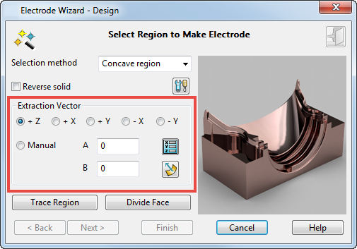
Extraction Vector — These options define the vector that is used when creating the electrode. You can use pre-defined vectors or create a custom vector by selecting the Manual option. Using one of the pre-defined vectors automatically inserts the correct values in A and B.
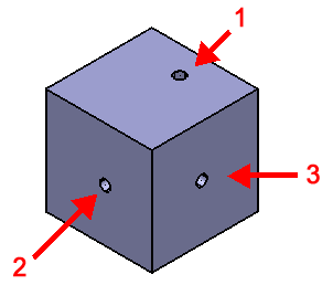
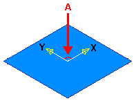
- +Z — This is the default and is used to create a standard Z-sinking electrode. Use this option to create an electrode for the hole in face 1. A yellow arrow indicates the direction of extraction:

- +X — Select +X as the extraction vector.
- +Y — Select +Y as the extraction vector.
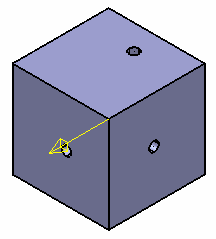
- -X — Select -X as the extraction vector. Use this option to create an electrode for the hole in face 2. A yellow arrow indicates the direction of extraction:
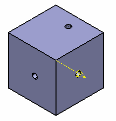
- -Y — Select -Y as the extraction vector. Use this option to create an electrode for the hole in face 3. A yellow arrow indicates the direction of extraction:
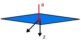
Manual — Manually create an extraction vector by assigning values to A and B or selecting the Position Vector  button. Use the Manual option to define a vector burn that is not aligned to an axis, such as the one shown below:

- A — The angle of rotation of the extraction vector in XY.
- B — The angle from the vertical. 0 is down the Z axis and 90 is a side-sparking operation.
— Opens the Position dialog. Use the Vector tab to define the extraction vector.
 — If selected, the burn vector is defined by clicking on a surface where the surface normal is in the required direction.