Learn how to define elements of structure like columns, beams and bracings using the previously added sections.
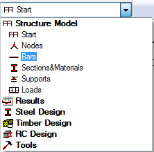
- In the Standard toolbar, expand the Layouts drop-down menu and select Bars as shown below:
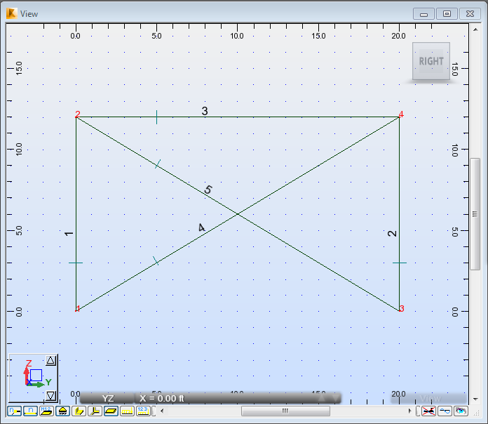
The layout is divided in three parts: View, Bars dialog and Bars table.
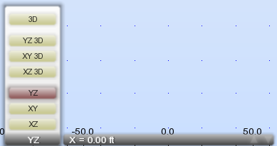
- At the bottom of the drawing area, expand the list of views, and then select the YZ view.
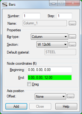
- In the Bars dialog, set the Bar type to Column and set the Section to W 12x96.
- To create the first column, enter the Node coordinates in the Beginning and End boxes as follows:
- Beginning: (0.00, 0.00, 0.00), Important: The coordinates syntax depends on your regional Windows format. In this tutorial we use the English (United States) format. If you want to change your Windows format, click: Start
 Control Panel Region and Language Format.
 - End: (0.00, 0.00, 12.00).
- Beginning: (0.00, 0.00, 0.00),
- Click Add.
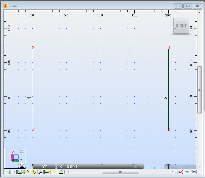
The column displays in the drawing area.
- Repeat this process to add the second column, with the following coordinates:
- Beginning: (0.00, 20.00, 0.00),
- End: (0.00, 20.00, 12.00).
- Click Add. The second column displays in the drawing area.
- Click
 (View Zoom Zoom All) to better visualize the defined columns.
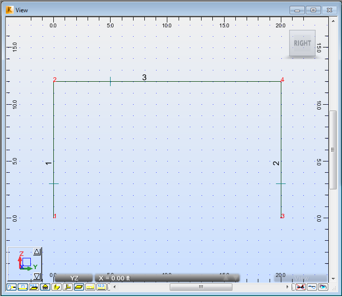
- To create the first beam, go to the Bars dialog, and then set the Bar Type to Beam, and the Section to HP 10x42.
- Enter the beam's coordinates, in the Beginning and End boxes as follows:
- Beginning: (0.00, 0.00, 12.00),
- End: (0.00, 20.00, 12.00).
- Click Add. The beam displays in the drawing area.
- To create the first bracing, go to the Bars dialog, and then set the Bar type to Simple bar, and the Section to LP 2x2x0.1875.
- Enter the bracing's coordinates, in the Beginning and End boxes as follows:
- Beginning: (0.00, 0.00, 0.00),
- End: (0.00, 20.00, 12.00).
- Click Add. The first bracing displays in the drawing area.
- Repeat this process for the second bracing with the following coordinates:
- Beginning: (0.00, 0.00, 12.00),
- End: (0.00, 20.00, 0.00).
- Click Add. The second bracing displays in the drawing area.