The Generate Complex tool is used to create Complex objects, which are a new way to represent material sub-regions inside a 3D solid. A Complex is a standard surface Mesh, combined with interior "sheets" of triangles that join to the surface mesh along edge loops. These edge loops are hence non-manifold, as each edge is connected to 3 triangles.
These Complex objects are a completely new concept in 3D design, which only exist in Meshmixer. In fact, we are still working on how to integrate them into Meshmixer. Some of our editing tools, like Remesh or Volume sculpting, have been extended to work properly with complexes. Once you have a complex, you can add additional sub-regions with the Meshmix drag-and-drop. However some other mesh editing tools can mangle your complex or even cause Meshmixer to crash. This is a work in progress, but it is useful enough that we decided to release Complex support in Meshmixer 3.0.
Note that the name Complex is not meant to indicate that these objects are more complicated (although they kind of are!). The name was inspired by Cellular Complex, which is a way of describing complex shapes composed of sub-regions ("cells"). We would have used Assembly instead, but that word is already very overloaded in CAD terminology.
The property panel for Generate Complex is shown below. In fact, none of these properties have any effect unless you have selected a sheet boundary.
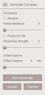
The panel has two sections, the Fill Options section above, and the Offset Options section below. You only have access to these controls when a Fill or Offset sub-region is selected, respectively. We will explain the properties in the relevant section below.
The Auto-Generate button can be used to try to automatically initialize a set of Fill regions based on the input model. An example is shown below.
Interface
The interface to Generate Complex is unlike any other tool in Meshmixer. The complex construction tools are based on face groups. Basically, you must predefine your material regions on the surface as face groups, and then Generate Complex will help you turn those face groups into internal material regions.
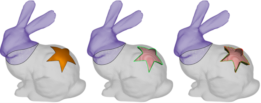
In the image below, on the far left we have our input surface mesh, with three face group regions (head, body, star). The next image shows the view when you begin Generate Complex, and move the mouse off the object. You will see a semi-transparent rendering with the boundary of each valid face group displayed as a thick black line.
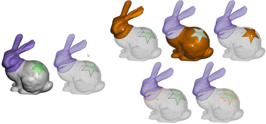
As you move your cursor over the object, the different areas will highlight. The top-right three images show the orange region highlights you will see as you move the cursor over the three different face groups. If you left-double-click on any of these regions, that area will be extruded inwards to create an Offset region. The bottom-right two images show the orange boundary-curve highlights you will see when you place the cursor over the face group boundaries. If you left-double-click here, you will create a Fill region.
Fill Regions
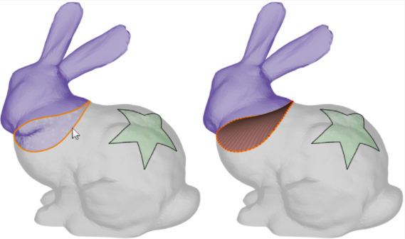
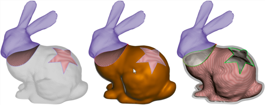
Fill regions are created when you double-click on a face group boundary curve. These curves demarcate the boundary between two existing face groups. The interior sheet that is created will fill in this boundary loop, through the interior of the object. The surface that is created is very similar to that produced by the Erase & Fill Tool. The image below shows the highlight on the left, and the fill patch that is generated on the right.
Offset Regions
You create an Offset region by double-clicking on a face group interior. The face group is then inset in the same way as the Edit > Extrude & Extract tool; however, rather than moving the initial patch we are moving a copy. Hence, an interior solid region is defined. The image below shows the highlight for the star region, then the initial Offset.
Conflict Resolution
One limitation of our current approach is that we do not support the same face group boundary loop being involved in both Fill and Offset regions. While this restriction may be lifted in the future, currently it prevents some very tricky situations which we have not figured out how to support. So, to enforce this constraint, when you try to create a Fill or Offset region that would conflict with its neighbours, we automatically update them so that your desired operation is allowed.
Output
When you Accept the current Generate Complex result, a new complex object is inserted in the scene, and your original surface Mesh object is hidden. The complex will have "(complex)" appended to its name.
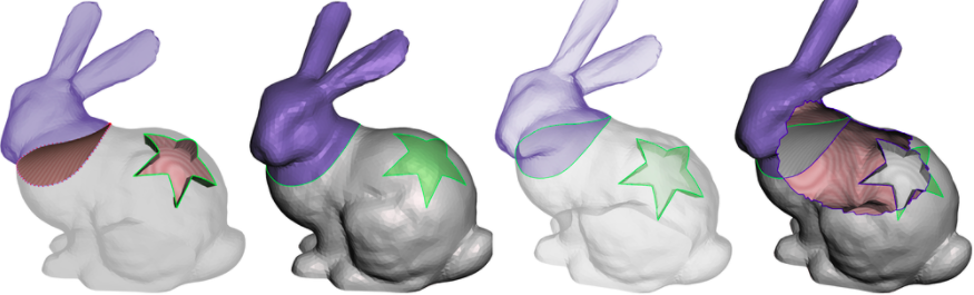
You can identify a complex object by the green lines drawn on the surface along the non-manifold boundary loops (below middle left). The two rightmost images show the Complex object with the XRay shader enabled, and then a view where some of the surface mesh has been deleted. In each you can see the interior sheets which define the interior solids. To convert the Complex into separate solids, you need to use the Split Complex tool, which is described in the Complex Tools topic.
Auto-Generate Button
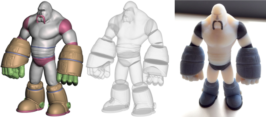
It can be quite tedious to manually click on each region if you have a lot of them. We currently support the capability to automatically assign a Fill region at each face group border, by clicking on the Auto-Generate button. In the image below, on the left we have a character mesh decomposed into roughly 30 face groups. The middle image shows an X-ray rendering after we have used the auto-generate. The rightmost image shows a multi-material 3D print of this design.
Limitations
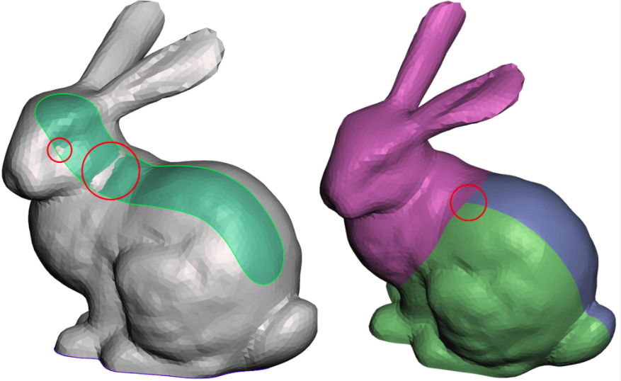
There are two major limitations of Generate Complex that you are likely to encounter. First, neither the Fill nor Offset regions are constrained to stay inside the surface mesh. For Offset you can resolve this by reducing the Offset Distance, but for Fill regions there is not much you can currently do. In the image below left, the Fill surface pokes through in the two circled areas. Note that for this face group, clearly an Offset region would be a better choice. In the image on the right, we have three face groups meeting at a junction point. Generate Complex currently does not support such a configuration. Group boundary curves must only be connected to two separate groups to work with the current tool.