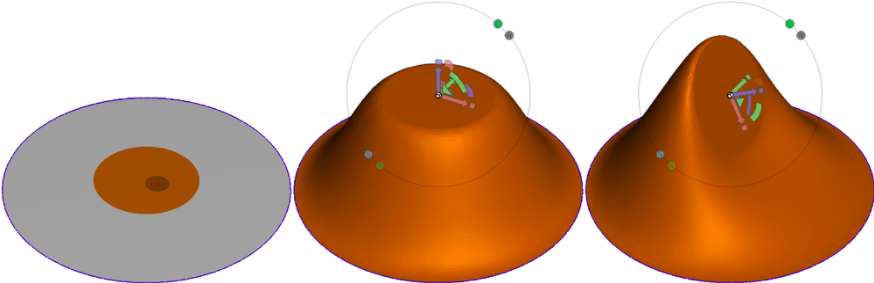
The Soft Transform tool is a variant of the tool. Like that tool, the area you select is rigidly transformed using the 3D manipulation widget. However, instead of connecting the transformed and original boundary loops with a tube of mesh, we apply a deformation to a region around your selection, to create a smooth transition. The image below shows a simple example, where a disc-shaped region is translated and then rotated. As you will see, this is quite a powerful deformation technique, that goes well beyond the simple deformers found in other 3D tools.
The hotkey for Soft Transform is Shift+t.
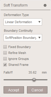
The property panel is shown below. As these settings have relatively complex effects, most are explained in detail below.
Deformation Type
Soft Transform currently supports four deformation types: Linear Deformation, Nonlinear Deformation, Flat Transition, and Stretchy Transition. These modes have quite different effects, and in particular, nonlinear mode has some complex limitations that we will discuss at length.
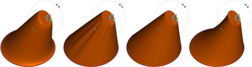
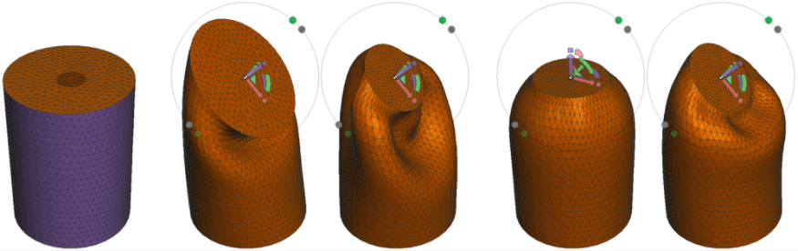
The image below shows an example similar to that at the top of the page, for each of the models in left-to-right order of Linear, Nonlinear, Flat, and Stretchy:
- Linear mode is the default and is most likely to create pleasing "soft" transitions.
- Nonlinear mode treats the mesh as a sort of "rubber sheet" that will have some physical-like behaviors, like the buckling in this case.
- Flat mode is a variant of Linear mode which attempts to minimize bending in the transition surface, although in more complex cases there will be some bending.
- Stretchy mode is also a Linear variant that behaves somewhat like pulling on a physical volume of clay, although this is by no means a volume-preserving deformation!
In the example above, the outer boundary loop was constrained to maintain its position. Soft Transform also allows for free boundaries. This next image shows such a case. The transformed region is a small strip on one side, and the falloff region is defined to be nearly the entire square, save for a small strip on the left (otherwise the entire sheet would move). The image second from left shows a Linear deformation, and the next image shows the Nonlinear variant. The out-of-plane buckling, which comes from trying to preserve the surface area of the square, is the non-linear effect.
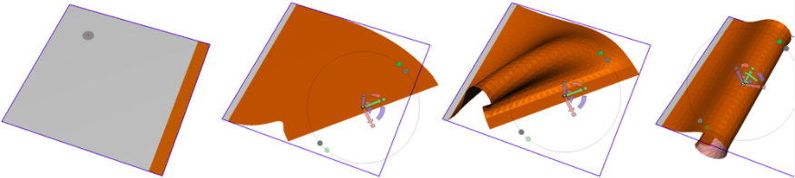
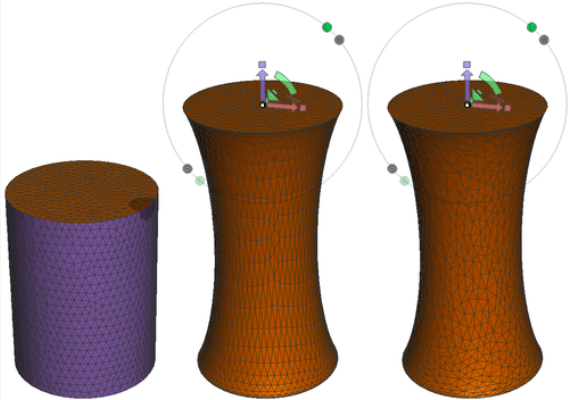
The rightmost image above shows another example where we use Nonlinear mode, applied to the same selection/falloff region, to roll the square into a tube. This is impossible with the Linear modes. The one serious caveat of Nonlinear mode is that the deformation configuration is dependent on the motions you took to get there. Below we have a cylinder in which the selected region is transformed to the same final state in two different ways: one a rotation then scale, and the other a scale then rotation. The final surfaces are very different!
This order-dependency is an artifact of how Nonlinear mode works. Internally, we are incrementally updating the deformation at each frame, based on the previous frame. This is necessary to provide reasonable performance, otherwise the deformation would be far too slow to use interactively. The trade-off is that different paths through the configuration space will usually lead to different results. This is also affected by speed of movement!! In most cases if you slightly wiggle the 3D widget, the deformation will continue to settle into a more ideal configuration (ie less bending). This is useful after Undo/Redo operations, which also do not work particularly well in Nonlinear mode.
Note that the Linear modes do not exhibit any of these behaviours. That is because for the Linear modes we can solve directly for the deformed configuration, rather than having to do so incrementally.
Falloff and Ignore Groups
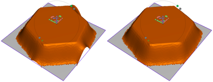
The shape of the falloff region is the most significant control you have over the Soft Transform tool. By default, the falloff is defined as a geodesic radius around your initial selection. In this case you can use the Falloff slider to grow or shrink the falloff region. However, you can also use face groups to specify more complex falloff regions. In the leftmost example below, we have a circular face group embedded in a star-shaped group. When we apply Soft Transform to the entire circle region (selected with the double-click shortcut), then the surrounding star-shaped face group defines the falloff region.
This is a powerful capability, as you can create much more complex deformations by changing the falloff region. However, if your selection is an entire face group but you would like to use a fixed-distance falloff, check the Ignore Groups button. This was done in the rightmost image below, and so the containing face group is ignored and a geodesic radius is used instead.

Boundary Continuity
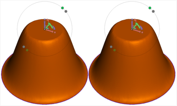
The Boundary Continuity drop-down has two options: SoftPosition Boundary and SoftTangent. There is very little difference between these modes. The goal of SoftTangent mode is to provide more continuous transitions at the borders of the falloff region. However in most cases you will have to look quite closely to see a difference. The image below shows a case where there is a small but noticeable difference.
Fixed Boundary
By default, Soft Transform does not constrain selected mesh boundary vertices. So, if your falloff region includes the mesh border, it will move, as in the image below left. If you want the boundary to stay put, enable the Fixed Boundary option, as shown below right.
Refine Mesh
Like Warp and Smooth, the Soft Transform tool's default behaviour is to only move the mesh vertices. The connectivity is not modified. You can enable auto-remeshing of the transition region with the Refine Mesh checkbox. However, you have no control over this remeshing, and if you are using facegroups to define the falloff then it will be very easy to do an explicit Remesh pass afterwards. So this option is not particularly useful.
Tips and Tricks
Like Warp and Smooth, Soft Transform is quite sensitive to the quality of the input mesh. If you have degenerate or non-manifold triangles in the falloff region, the tool may fail. In this case you will likely see the transition region disappear. The smoothness of the deformation in the transition region is also sensitive to triangle quality, and you will need sufficient mesh density to capture the shape transformation. However, this tool also can get quite a bit slower if the mesh is extremely dense in the falloff region.