The continuity equation is used to calculate the flow rates in the channel network.
In general, the fluid density
 may vary in response to changes in fluid temperature and pressure. For a fixed control volume,
 , enclosed by a surface, S, a general statement of mass conservation is given by:
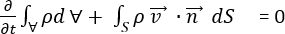
where
 is the velocity at a point,
 is an outer unit normal vector to the surface, S, and
 is time.
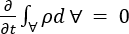
The first term represents the accumulation of mass in the control volume over time. For steady state flow, the first term
At a surface point, the dot product
 gives the component of the velocity which crosses the surface. Hence the second term gives the net outflow of fluid across the entire surface of the control volume.
Continuity equation
For steady state compressible flow of fluid in a pipe or duct the conservation of mass is referred to as the continuity principle, and can be written by the continuity equation as the product of the density,
, of the fluid of mean velocity, V, at any cross sectional area, A, of the pipe or duct, or:

where
 is the mass discharge through the pipe or duct, and Q represents the volumetric flow rate in the pipe or duct.
The continuity equation needs to be satisfied on every node in the network.
Solving the continuity equation for each node
Referring to the coolant flow computational domain, the continuity equation can be expressed algebraically at each internal node by:
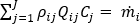 for
i
=1, ...Nodes,
j
=1....Branch elements
for
i
=1, ...Nodes,
j
=1....Branch elements
where
= 0 for all internal nodes, and
= the mass flux entering or leaving the network for a given boundary node.
 refers to the connectivity operator, (+) or (-), for the given branch of the node under consideration.