In order to solve the flow in the cooling circuit, the correct pressures need to be computed on each node together with the correct flow rates in each element of the circuit.
The Coolant Flow analysis is based on two simple principles:
- Continuity Principle
- The conservation of mass throughout the system must be satisfied, by ensuring that the total flow into a junction is equal to the total flow out of the junction for all junctions in the network. In addition to this, the total flow rate must remain constant in pipes or ducts connected in series, regardless of the changes in diameter. This principle is described by the continuity equation, and explained in subsequent pages.
- Work Energy Principle
- The pressure drop between two junctions must be the same for all paths between the two junctions. This principle is described by the work energy equation, and modified to include contributions from head loss, minor losses, and any pumps present in the circuit. These derivations are described in subsequent pages.
To solve the temperatures and pressures on each node in the circuit, and the flow rates on each element, these equations need to be solved simultaneously. The derivation of each is described in more detail on subsequent pages. When presenting the following equations it should be noted that the index i refers to the nodes of the network and the index j to the branches of the elements attached to the node, as described in Coolant flow computational domain.
Continuity equation for flow rate
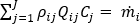
The continuity equation needs to be satisfied at each node:
 for
i
=1, ...Nodes,
j
=1....Branch elements
for
i
=1, ...Nodes,
j
=1....Branch elements
where
 is the fluid density, Q represents the volumetric flow rate in the channel, and
 refers to the connectivity operator, (+) or (-), for the given branch of the node under consideration, as described in
Coolant flow computational domain.
refers to the connectivity operator, (+) or (-), for the given branch of the node under consideration, as described in
Coolant flow computational domain.
 , the mass flow rate, = 0 for all internal nodes, and
= the mass flux entering or leaving the network for a given boundary node.
, the mass flow rate, = 0 for all internal nodes, and
= the mass flux entering or leaving the network for a given boundary node.
Work energy equation for pressure drop
The flow rate pressure drop relationship must be satisfied at each branch element connected to each node, as described by the generic work energy principle equation:
where
 is the pressure drop flow rate relationship derived from the work energy principle equation
 ,
,
 is the connectivity operator, (+) or (-),
is the mass flow rate, and
is the connectivity operator, (+) or (-),
is the mass flow rate, and
 is a function of the density of the fluid in the network. For incompressible fluids, such as water, this is a constant.
- Including frictional head loss and minor losses
-
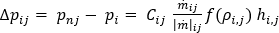
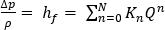
However, mold cooling circuits are subject to both head loss and minor losses, so a more specific version of the flow rate pressure drop relationship is used. Head loss due to fluid shear is a function of fluid flow in any straight pipe. The Darcy-Weisbach equation calculates the pressure drop due to friction in a straight length of pipe or duct. Minor losses are the pressure losses attributed to the fluid flowing through fittings, valves, bends, elbows, tees, inlets, exits, enlargements and contractions. The generic work energy principle equation can be modified to include frictional head loss and minor loss, as:

where
 is the friction factor, D is the diameter of the channel, L is its length , K is the resistance coefficient and can be obtained from the manufacturer, A is the cross sectional area of the channel, and Q represents the volumetric flow rate in the channel.
is also independent of the Reynolds number.
- Including a pump
-
When the branch has a pump or fan element attached to it, the relation that applies is:

Elevation is considered on the boundary nodes, when you choose to include gravity in the calculation. This option is off by default.
Temperature equation
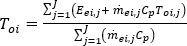
The temperature at each node is obtained from the total energy of the fluid entering that node, and is given by:
where
 is the fluid temperature, and the right-hand side of the equation refers to the branch elements.
 is the specific heat of the fluid,
 is the energy transfer to element e, and
is the mass flow rate in the element.
is the energy transfer to element e, and
is the mass flow rate in the element.