Cooling circuits typically involve several channels or channel components connected to each other in series or in parallel. The analysis of fluid through these circuits is based on two simple principles; the continuity principle, and the work energy principle.
- Continuity Principle
-
The conservation of mass throughout the system must be satisfied.
For channels connected in series, this means that the total flow rate remains constant, regardless of changes in diameter or cross sectional shapes of individual components of the system.
For parallel flow, this means that the total flow into a junction is equal to the total flow out of the junction for all junctions in the network.
- Work Energy Principle
-
The pressure drop between two junctions must be the same for all paths between the two junctions.
With series connection, the total pressure loss is equal to the sum of all the pressure losses in the individual components in the series system. In large systems the main contributor to pressure loss is frictional losses in the network, but minor losses caused by the fluid flowing through fittings, valves, bends, elbows, tees, inlets, exits, enlargements, and contractions etc. also contribute. In smaller system, such as molds, the contribution from minor losses is more significant.
For parallel channels, the pressure losses in each branch connected by the same two junctions is the same. The relative flow rates in each parallel branch is established from the requirement that the pressure loss in each branch be the same.
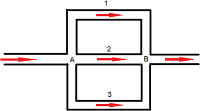
Figure 1. Parallel flow through a network
For example, the work energy principle states that the pressure loss through all three branches in Figure 1 is the same. However, coolant has further to travel along branches 1 and 3 to reach the same junction B. Since flow always follows the path of least resistance, for the same pressure loss, more fluid flows through branch 2 than through branches 1 and 3. The total flow through the network is the sum of the flow through branches 1, 2 and 3. So, the head loss is the same in each branch and the total flow rate is the sum of the flow rates in all the individual pipes or ducts.