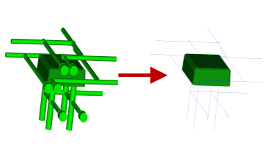
Extract center line curves from imported 3D CAD cooling channel bodies. Use these curves to construct beam elements used for the modelling of most cooling channels.
Cooling channels are often designed in a CAD package and imported into Autodesk Moldflow as 3D bodies. Most analyses require the cooling system to be represented as beam elements.
Convert the 3D bodies into beam elements by first extracting the center line curves of the 3D bodies and then building beam elements along the curves. The channel diameter specified in the CAD design is automatically inherited by the created curve, along with a property of Channel.
Drafting issues
3D bodies can appear to be joined but are not completely connected. This will cause breaks in the center line.
Check the connectivity of the extracted curves. Create curves to manually repair any breaks. There can be many channels in a complex mold. Work on a single channel at a time to simplify locating any problems.
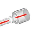
The image above illustrates enlarged openings at the start or end of the channel. This larger body is to accommodate the coolant hose connector and the smaller body is tapered to improve the engagement of the connector thread. Tapered sections are not supported, causing the break in the red line which represents the extracted center line. Remove both of these bodies for a simpler analysis.
Stagnant areas
Cooling channels are usually manufactured by drilling holes from the outside of the mold, that intersect with other holes. The construction section of the channel is then plugged causing an area of stagnant coolant.
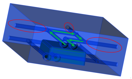
Models with stagnant areas need both an inlet and an outlet specified so that the program can determine the coolant flow path. Do not remove the construction channels from the model as the stagnant coolant in these areas heat up and impact on the heat of the system.
Non-circular cross-sectioned channels
Regular non-circular cross-sectioned 3D CAD bodies have center line curves extracted and placed through the centroid of the shape. These center line curves do not have any properties assigned. To represent these curves as beams, an equivalent diameter and a Channel property has to be applied before meshing. If the equivalent beam intersects with the part or a mold component, the analysis cannot run. Flat channels are often not supported for this reason. Consider running models with non-circular cross-sectioned 3D CAD bodies as a conformal cooling analysis.
Bubblers and Baffles
Extracted center line curves that represent bubblers or baffles are assigned the property of Bubbler or Baffle. On meshing, these curves are converted into the appropriate element. The coolant flow is automatically modeled to flow correctly through these elements.
Limitations
- Tapered 3D bodies are not supported.
- Non-circular channel cross-sections may not be supported. Conformal cooling can be used to analyze these models.