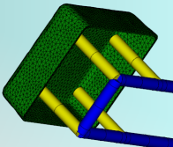
Create elements along a manually created curve to represent a baffle.
Note: Baffles can also be modeled at time of meshing by extracting center lines from an imported CAD model of the cooling system and assigning a property of Baffle to the appropriate curves
It is assumed that:
- The cooling channel curves have been defined
- A baffle is to be added to one or more of these curves
- There is not a node on the cooling channel curve where the baffle is to be created.
Note:
For a Cool (BEM) analysis, when cooling elements pass through an insert that has different thermal properties to the rest of the mold, the insert material needs to be specified and applied to those elements.
Nodes may need to be placed on the cooling channel curve at the boundary of the insert so that affected elements and the insert align. Apply a different property to the impacted elements so that the insert material can be easily applied.
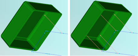
- Click
 () and place a node at the baffle origin.
- Click
 () and create a line from the node towards the part. End the curve a distance from the part that is at least equivalent to the diameter of the baffle.
- Select the curve that represents the baffle. Click .
- Enter the baffle dimension in the Baffle Surface Properties tab of the Baffle dialog.
- Enter 0.5 for the Heat transfer effectiveness (HTE).
- Select the mold material from the options in the Mold Properties tab of the Baffle dialog. If the baffle is encased in a different material to the rest of the mold, it is important to specify that material.
- In the Name box, enter an appropriate name for the baffle, then click OK twice.
- Click
 (), and click
Mesh Now.
(), and click
Mesh Now.