A local coordinate system (LCS) is a set of x, y and z axes associated with each node in the model. It is often preferable to use a local coordinate system for assigning constraints and loads to simplify the constraint or load to one direction.
With the Local Coordinate System tool, you can create and save multiple local coordinate systems, but only one can be active at a given time. All subsequent modeling will be created relative to the active LCS. If you activate the LCS as a modeling plane, new geometry will be created in the new xy plane for easier modeling. You can also activate the LCS for results visualization, when studying warp and the effects of stresses and strains.
Definition
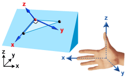
To define a local coordinate system you need three reference points or nodes in the model. Given three reference locations the x, y and z axis is defined as follows:
- Coordinate 1 defines the origin
- Coordinate 2 defines the local x direction
- Coordinate 3 defines the xy plane, with the local Y axis passing closest to coordinate 3
The local z direction is defined to be perpendicular to the xy plane, such that the local coordinate system is "right-handed".
- Specify only Coordinate 1 to define a local coordinate system where coordinate 1 is the origin, and local axes are in the same direction as the global axes.
- Specify Coordinate 1 and Coordinate 2 to define a local coordinate system with a defined origin and a local x axis in the direction from coordinate 1 to coordinate 2. The y and z axis directions will be selected automatically.
- Specify all three coordinates to define a local coordinate system with a defined origin and defined local axis directions as given by the right hand rule.