Generate a voxel mesh and adjust its settings.
This video explains how to preview the mesh, examine it in cross section, and adjust the level of detail.
Video length (4:51).
Follow the step-by-step instructions shown in the video. Sample files for use with the tutorials are available on the Download Page.
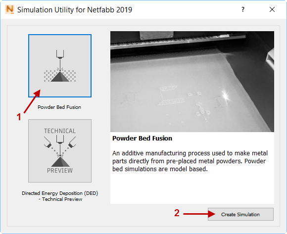
- Click .
- In the dialog that opens, click
Powder Bed Fusion and then
Create Simulation.
- In the Import model dialog, browse to and open the sample file Example_4.stl.
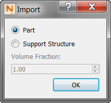
- In the
Import dialog, click Part, and OK.
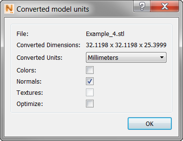
- In the
Converted model units dialog, ensure that
Converted Units are
Millimeters and
Colors is not selected, then click OK.
- Click
.
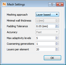
- Switch the Meshing Approach to Layer based, if necessary. Make sure the Coarsening generations are set to 1 and the Layers per element are set to 20. A coarsening generation is a level of adaptivity from a fine element to a coarser element. This process allows for faster simulations by drastically reducing the number of degrees of freedom required for a model. The finest element size is specified by how many layers are grouped per element sized. Consult Mesh Settings for additional details about how these controls function.
- Click
and you are prompted to confirm the file name and location. Change these if you wish. When you click Save, the mesh generation begins. When the analysis is completed, the mesh appears.
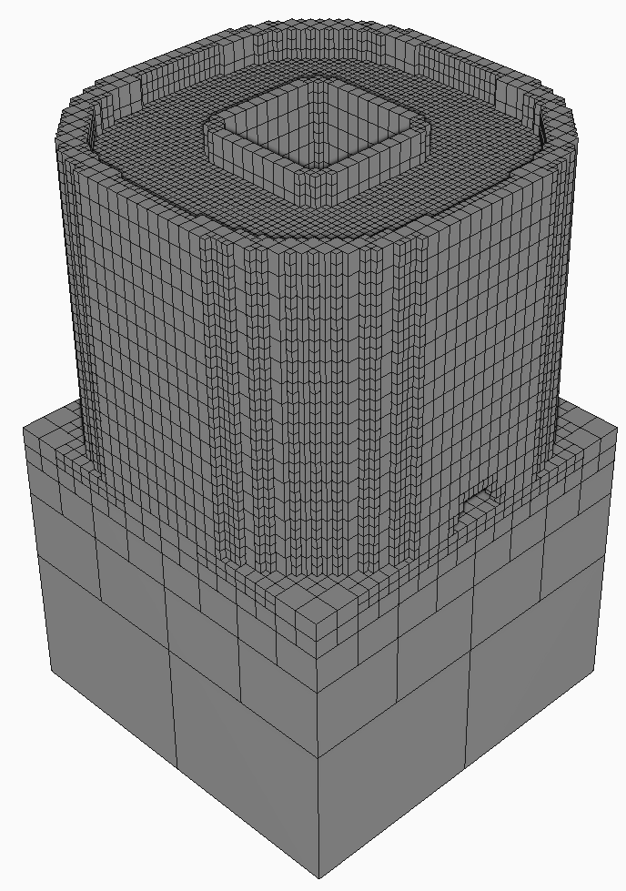
- Click
 .
.
- In the
Edit Clipping Plane dialog, click
Snap to: ZX or one of the other axes combinations to get a good cross-section view of the mesh.
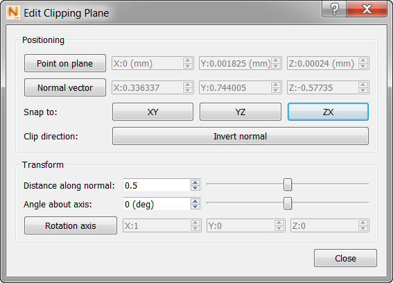
If the cross section is facing away from you, click Invert Normal to see it correctly.
- Close the
Edit Clipping Plane dialog to more clearly see the clipped object.
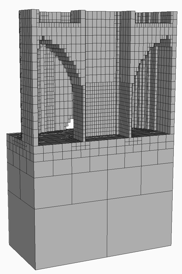
Note that the outside wall of the part has a width of one voxel. As a general rule choose mesh settings that create at least 2 elements through the thinnest feature of interest, so that the part can distort freely, without artificial stiffening.
- Return to the and set Coarsening generations to 1 and Layers per element to 10.
- To generate a new mesh, click
, and choose to invalidate existing results.
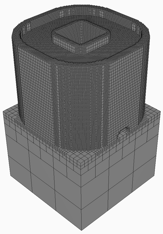
This time you should see a mesh that is noticeably finer in resolution.
- To examine the cross-section details, click
again.
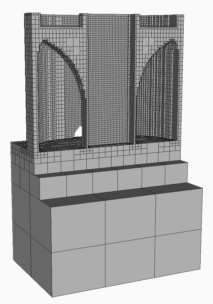
Now the outside wall should have two elements through the cross section. Note also that the resolution of the mesh varies by region. Critical areas of the part, such as curves, are rendered with small voxels, while the inside of the build plate uses larger elements, with hanging or constrained nodes. This adaptive mesh resolution allows Simulation Utility to generate both preview meshes and full simulations very quickly.
In the Browser, results for a Mesh preview include a Structure type display so that you can see the build plate mesh in a different color than the part mesh.
For a related tutorial on how to adjust mesh settings to comply with the limitations of Simulation Utility LT, see Tutorial 21.