Loading and saving CAD files, and managing a CAD file's parametric data
To Recognize a Parametric Part
Check the part's icon in the
project tree. Parametric parts are represented with a
 cylinder, pure mesh parts show up as a
 shaded circle.
 Retessellate model or
 Remove parametric association are greyed out, it's a pure mesh part.
Your workflows in Netfabb will remain largely unaffected as long as you do not change part shape by operations such as cutting or mirroring. When attempting to perform such actions, you will be warned with a dialog to tell you that this will drop the parametric information from the part. You may disable the warning dialog by setting to No. Dropping the parametric information fixates the current tessellation permanently into the part's mesh.
 You can convert the mesh back into a parametric model using
Modify >
You can convert the mesh back into a parametric model using
Modify >  Mesh to BREP.
To Drop the Parametric Data
You may manually force to drop the parametric dataset, and turn the CAD part permanently into a triangle mesh, at any time by choosing
Prepare > Remove parametric association.
To Load a CAD File for Native Use
Choose
File >
 Add Part from the main menu.
 Open File from the toolbar to do the same.
Export Parts as Parametric CAD File
- In Netfabb, select the parts you want to export.
- Click
File >
 Export Part > as parametric model file (SAT, STEP, IGES), and select the CAD format you want to export to, SAT, STEP, or IGES.
The Export Parts dialog box opens.
- Adjust export settings for the parts.
- Enter a name and folder for your file and click OK.
To Retessellate a Part
To retessellate the part for a workflow step that could benefit from a different level of mesh resolution, choose
Prepare >
Retessellate model. This will provide you with a dialog to choose from tessellation presets.
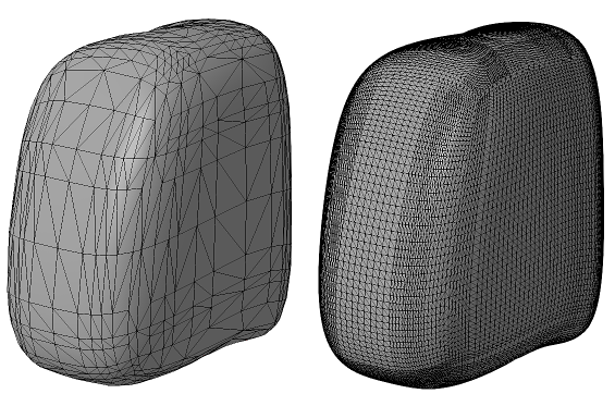
The same part, tessellated with two different presets
To Create and Modify Presets
Netfabb comes with a set of tessellation presets as well as a variant for each that includes repair. To create and modify presets, do so during retessellation, or choose
System > Tessellation setting library.
Here, you may create and edit duplicates from the default presets (these cannot be modified). Provide a name and make your selection from these options:
| Parameter | Description |
|---|---|
| Normal tolerance |
The smaller the tolerance, the more triangles will be generated to replicate curvature of a surface. |
| Surface tolerance |
The smaller the tolerance, the more triangles will be generated to replicate a face shape in general |
| Maximum edge length |
Limits the length of triangle edges |
| Maximum grid lines |
Grid lines are an internal method to aid in triangle generation. |
| Minimum grid lines | |
| Smoothing mode |
Applies smoothing to no, surrounded, or all interior mesh nodes. |
| Triangulation level |
Sets the level of triangulation in some edge cases. |
| Intersection mode |
Intersections of grid lines may be used to provide additional points for meshing. |
| Postprocessing mode |
Choose a preference for regular triangles or quads, if required. |
| Calculation mode |
Prefer approximation and faster calculation, or higher accuracy and increased calculation cost. |
| Repair mode |
Select from six options for post-tessellation repair, including Netfabb's built-in default repair scripts. |