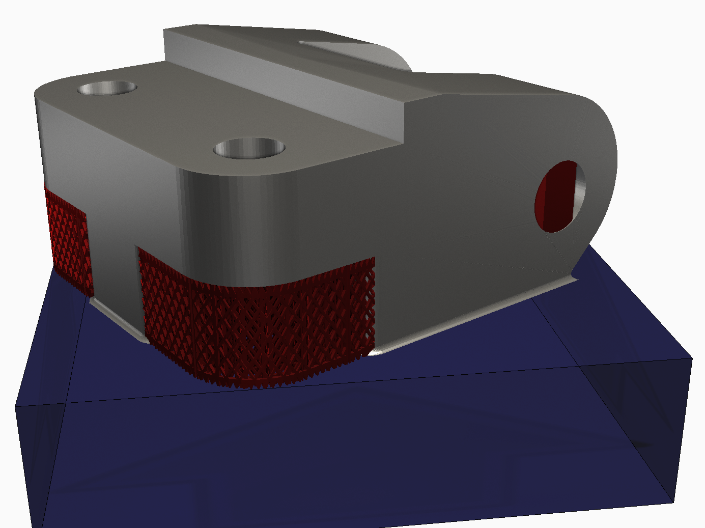
Create two different types of support structures in Netfabb and test their performance in Simulation Utility.
Video length (6:22).
Videos are not available in the offline help. Refer to the online help to watch the video.
Sample files for use with the tutorials are available on the Download Page.
In some cases, users may want to simulate both the preferred homogenized type supports, covered in Tutorial 15, and also the actual fine structured support, on the same model.
We will use Netfabb to create support structures for this part. Sample files for use with the tutorials are available on the Download Page.
- In Netfabb, click .
- If it's not already there, add
Generic Open Machine to your list of machines.
- In the My Machines dialog, click the Add Machine button.
- In the
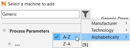
Select a machine to add dialog, enter Generic in the top field, click the Filter icon, and select the A-Z results display.
- Under the Process Parameters list, click Generic Open Machine, then click the Add to My Machines button at the bottom of the dialog.
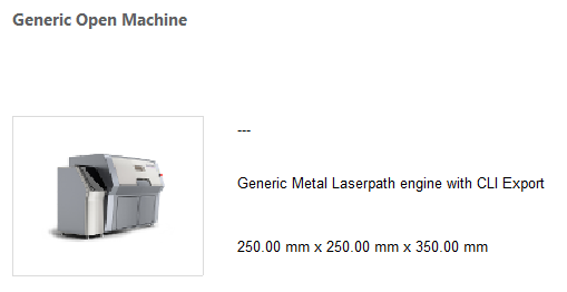
- In the
My Machines dialog, with the machine selected, click
Open.
You should see Generic Open Machine selected at the top of the project model tree.
- Click and add the sample file Example_22.stl .
- In the left pane, make sure that Force above platform is not checked.
- To check the part position in relation to the platform, at the top of the window click
Move Parts
 and note the Z value.
It is important for this exercise to place the part directly on the platform, not above it. In the example below of the Move Parts dialog, the part's Current Position has a Z value of 1.70 mm, so we must bring this to 0.
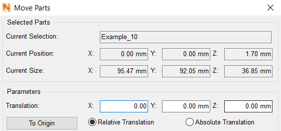
Use the Translation Z field to move the part. You can either select Relative Translation and set the Z value to –1.7 mm, or select Absolute Translation and leave the Z value at 0.00 mm, then click the Translate button at the bottom of the dialog.
- Click
Create Supports.

- At the bottom of the window, click
Run Support Script, in the
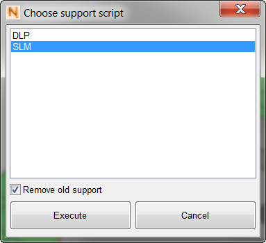
Choose support script dialog, select
SLM, and click
Execute.
The lattice-like supports are created.
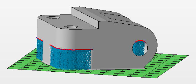
- For this instance, it is desired that only the back supports are homogenized. Click on the two front support and press the Delete key or right click the selected supports and choose
Remove entity.
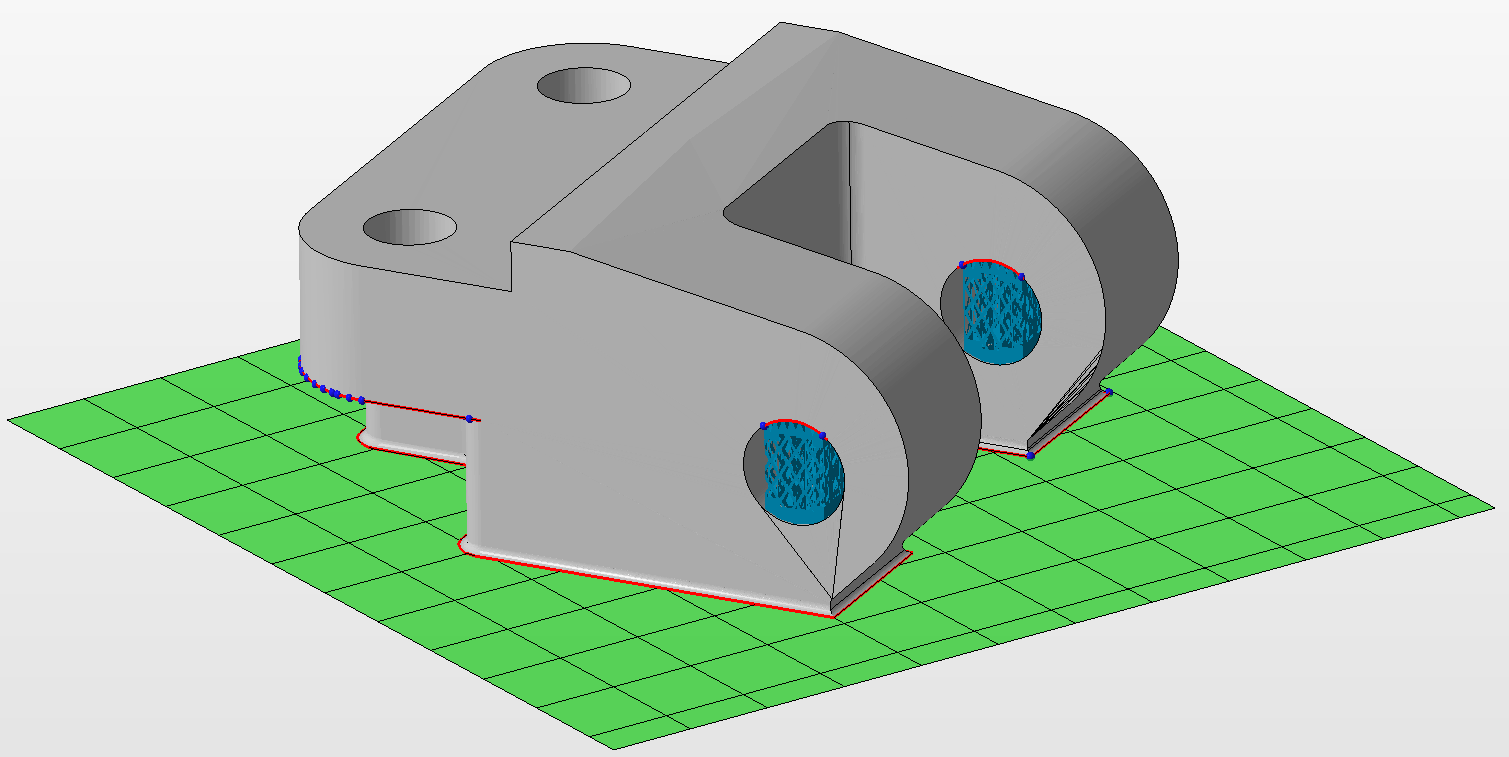
- Click Apply support.
- Click Start build simulation; in the dialog that opens, enter a suitable file path and name, such as Example_22, leaving in place the file extension .3mf. Click Save.
- In the
Start build simulation dialog, ensure that
Combine support volumes for simulation is checked, select the
Simulation Utility version, if both are available, and click
Simulate.
The exported file takes a minute or so to generate, then opens inside the Simulation Utility window.
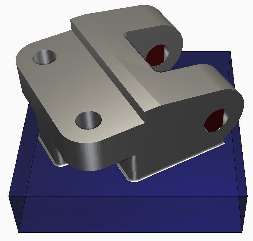
- Return to Netfabb to add the lattice type supports. Press Cancel to get rid of the send to simulation window.
- In the file tree, drag and drop the Example_22 part from the Generic Open Machine workspace to the Parts workspace.
- Press the
Generate Supports Icon
 or Navigate to
Prepare >
Generate Supports
or Navigate to
Prepare >
Generate Supports
- Click Run Support Script at the bottom of the Support Window. Choose SLM type supports from the list and click Execute.
- Now delete the back supports which have already been generated and homogenized.
- A thickness must be added for the lattice supports to mesh. Select both supports by Ctrl-A or clicking with the mouse while holding down the Ctrl button.
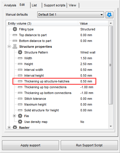
- Switch to the Edit tab in the Supports Menu. Expand the Structure properties menu by pressing the + symbol.
- In the
Thickening up structure-hatches field type
0.50. This will create support structure walls approximately 2-3 bead widths wide. Click
Apply support.
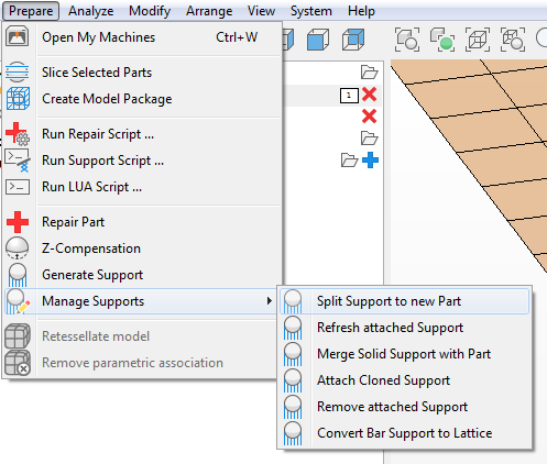
- To use in simulation, these supports need to be turned into an STL file. Navigate to
.
- Either in the file tree or canvas window, right-click on the new part with (support) in its name. Select
. Navigate to the same folder where the first Example_22.3mf file was saved. Name the new file
Example22_support.stl and press OK.
Note: Upon exporting, there may be a prompt to Optimize the part to ensure a good STL. Click Optimize and then Export when given the green check mark.
- Return to the
Simulation Utility window from step 11. From the Document panel on the Home tab, click
Import. Select the
Example_22_support.stl file just created. Designate this as a Support Structure with a Volume Fraction of
1.00 when prompted. Now you have a part with two types of supports, and you can proceed to perform a simulation as outlined in previous tutorials.