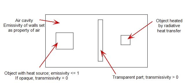
The radiation model supports radiative heat transfer through transparent solid media. The transmissivity material property defines the level of transparency of a solid object. Radiative heat transfer through a transparent solid object that is completely surrounded by fluid can be simulated by assigning a non-zero transmissivity property to the material. Opaque solids that are enclosed by transparent solids can be modeled as well. This even allows “nesting” of multiple layers of opaque and transparent solids.
In the radiation model, radiative energy that passes through a transparent solid does not experience an attenuation effect--there is no absorption of radiative energy into the media. There is no accounting for spectral effects within a transparent object, and energy leaves the object in a diffuse manner. Energy may, however, be absorbed through the surface and then emitted (emissivity = absorptivity). The energy balance for radiative heat transfer looks like:

where the reflectivity = 1 - emissivity - transmissivity
For more about creating custom materials...
Internal Transparent Parts
To include radiative heat transfer through a transparent solid that is completely surrounded by a fluid, assign a non-zero value of transmissivity to a custom material. For more about creating custom materials...
Note that the sum of transmissivity and emissivity must be less than or equal to 1.

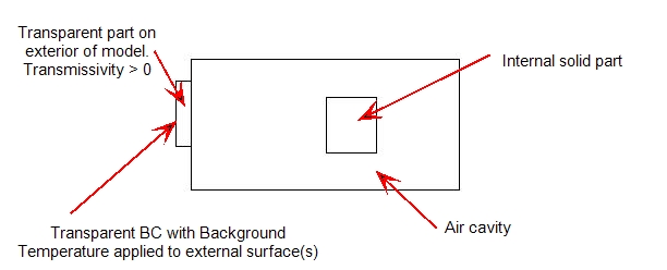
External Transparent Parts
To include radiative heat transfer through a transparent surface on the external wall, such as a window:
- Model the transparent region as a solid part.
- Assign a transmissivity value to a custom material using the Material Editor. (Note that the part must have a non-zero transmissivity property to be considered transparent.)
- Assign a Transparent boundary condition to the external surface:

The temperature specified with this boundary condition is used to define the incoming radiation flux according to this equation:

Transparent BCs should only be applied to external boundaries so that the incoming flux is external to the analysis domain. They must be assigned to a solid material; assignment to a fluid material will result in an error.
Solar heating problems should not use transparent BCs because the set up of the solar heating problem requires a sky dome and ground structure that define the entire external boundaries. If windows are modeled in these cases, these transparent materials would be internal to the analysis domain which would make transparent boundary conditions inappropriate.
If a transparent material with surfaces on an external boundary are not assigned a transparent boundary condition, the emissivity and transmissivity will automatically be set to 0. Because reflection is the difference between 1 and the sum of emissivity and transmissivity, the external boundary will be perfectly reflective (like a silver backing on a mirror) with the exterior of the model. This is done to conserve energy. Because no background temperature is defined, the heat loss/gain cannot be computed.
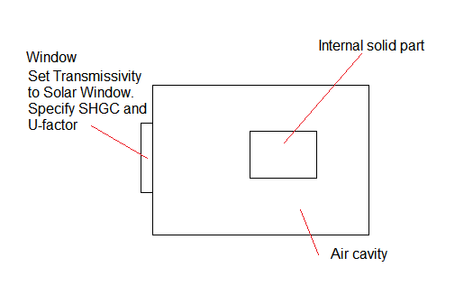
Transparent Parts with Solar Heating
To include Solar Heating through an external transparent surface, such as a window:
- Model the transparent region as a solid part.
- Select the Solar Window variation for Transmissivity, and assign values for the SHGC and U-factor to a custom material using the Material Editor.
- Enable Solar Heating on the Solve dialog. On the Solar Heating dialog, specify the simulation date, time, and location, and specify the ambient temperature or time variation.
