You can use the Autosize tab of the Mesh Settings dialog to remove parts from the simulation model by suppressing them. The dialog also contains a set of tools for controlling the mesh distribution to suit the details of the model and the needs of the simulation. You can control the number of elements across gaps, as well as several additional parameters and constraints that fine tune the overall mesh distribution. The Autosize button is the primary tool for computing the mesh distribution.
Part Suppression
Use the Part suppression tools for omitting one or more parts from the simulation model. You should suppress parts before applying Autosizing. For more about part suppression...
Gap Refinement
Gap Refinement controls the mesh within gaps between closely oriented surfaces, even if they belong to different parts.
- It meshes critical gaps with a fine mesh, and smaller, less relevant gaps with a coarse mesh.
- It improves the accuracy in small clearances and the heat transfer in thin solids.
- By focusing mesh in essential gaps, it improves solution accuracy and performance.
- Gap Refinement ignores flow openings (pressure, velocity, etc). If you have two openings with a small gap between them, Gap Refinement does not modify the elements in the gap. Mesh Adaptation can help in these situations.
Autosize Basis
The Autosize Basis dialog contains several controls for fine-tuning the mesh distribution.
Minimum Mesh Size
The Minimum Mesh Size provides control over if and how much smaller geometric features affect the rest of the mesh. This setting does not remove small features, but rather can limit their effect upon local length and mesh scales.
To increase the refinement on small features, and therefore increase their effect in the model, reduce the Minimum Mesh Size to a value smaller than the length of the particular feature. This improves the mesh on very small features, but may increase the number of nodes and elements in your analysis model. This is necessary if important edges fall below the default Minimum Mesh Size. Features that are larger than the default Minimum Mesh Size are meshed finer, and affect neighboring geometry.
To decrease the refinement on such a feature, and therefore reduce its effect on the model, increase the Minimum Mesh Size to a value greater than the size of the particular feature. Features that are smaller than the default Minimum Mesh Size are meshed coarsely, and do not affect neighboring geometry.
Changes to the Minimum Refinement Length affect the model globally, and are not isolated to a particular location. Care must be taken so that the Minimum Refinement Length is not accidently made larger than other important edges elsewhere in the model. Doing so will effectively remove their influence on the mesh, and may lead to accuracy issues.
Note that if the Minimum Refinement Length is changed after applying Automatic Mesh Sizing, the mesh distribution must be reapplied by clicking the Automatic Size button. Otherwise, the new Minimum Refinement Length will not affect the mesh distribution.
Maximum Mesh Size
Use the Maximum Mesh Size to limit the size of the largest elements in the mesh. This is useful for ensuring that the mesh is no bigger than a specific feature or detail size so that such geometric features are resolved appropriately for the simulation model.
Resolution factor
The Resolution Factor controls the relative fineness of the mesh in response to the curvature of model entities. Though this parameter has global scope, the effects are localized to regions of high curvature.
Smaller values result in a finer mesh on model entities with curvature. Regions with no curvature are not affected by this parameter.
The default value is 1.0, and the acceptable range is between 0.1 and 3.0. Values outside of this range are rejected.
Surface growth rate
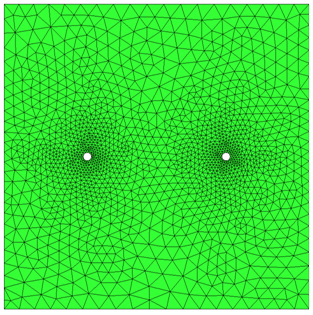
- To control the growth of surface elements, modify the Surface growth rate. The default value of 1.15 causes surface elements to grow by 15%:
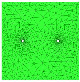
- Increase the Surface growth rate to reduce the resultant mesh density. A value of 1.4 was used below:
Wall layers growth rate
To control the growth rate of elements within mesh enhancement layers, modify the Wall layers growth rate. The default value of 1.05 allows the layers to grow by 5% from one layer to the next.
Gap refinement
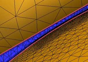
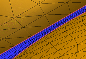
- To control the approximate number of elements across a gap (not including the mesh enhancement layers), enter a value for Fluid gap elements.
|
Fluid gap elements = 4 |
Fluid gap elements = 1 |
|
|
|
- To control the mesh in thin solids, enter a value for Thin solid elements.
- To prescribe more than one element across thin solids, specify a value of 2 or greater. For accurate temperature prediction, there must be at least two elements across all solid parts.
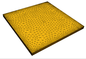
- To force a coarser mesh in thin solids, specify a value less than 1. The reciprocal is how much the surface faces grow relative to the volume elements. (A value of 0.2 causes the surfaces faces to grow 5 times larger than the tetrahedral elements.)
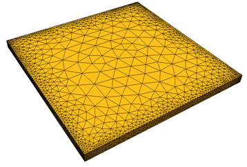
- To specify the size of the smallest gap that is meshed with the specified number of Fluid gap elements, modify the Gap refinement length. The minimum value of the slider is the smallest gap in the model. The maximum value is the Minimum Refinement Length computed by Edge Diagnostics, but can be modified if necessary.
- To mesh important gaps with a fine mesh, reduce the Gap refinement length smaller than the gap:
- To mesh irrelevant gaps with a coarse mesh, increase the Gap refinement length larger than the gap:
- The Gap refinement length applies to all gaps in the model. It is not possible to target individual gaps for refinement.
Wall layers
Use the Wall layers dialog to control the growth of element layers along the wall. For more about wall layers...
Autosize
Click Autosize to compute the mesh distribution throughout the model.

