Parasolid and Acis-based CAD systems include:
- Autodesk® Inventor (Acis)
- Autodesk® Inventor Fusion (Acis)
- Autodesk® Revit (Acis)
- Solid Edge (Parasolid)
- Unigraphics (Parasolid)
- SpaceClaim (Acis)
- UGNX (Parasolid)
- Solid Works (Parasolid)
- CoCreate (Acis)
The Internal Flow Volume
The internal flow volume is created when the openings of an internal flow geometry are capped with either a surface or volume and then read into Autodesk® CFD or within the product by using the Void Filling Geometry Tool.
Capping within the CAD model is illustrated below:
Step 1: Pipe geometry--only the physical solids exist (pipe wall and poppet):
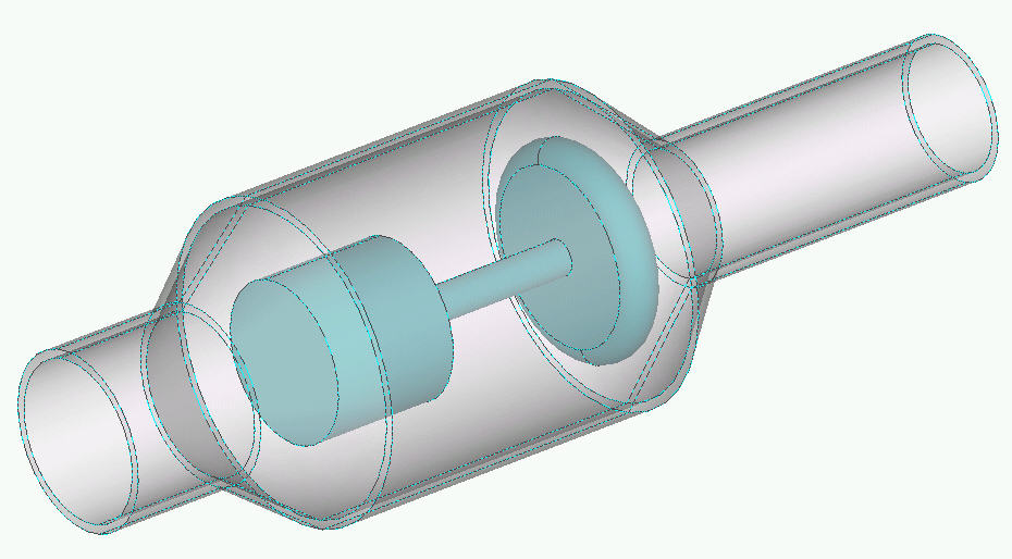
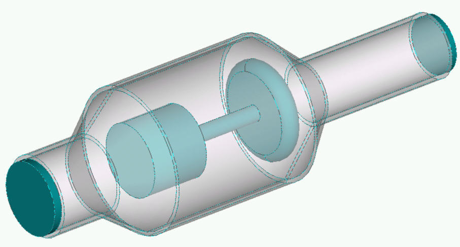
Step 2: Pipe geometry with newly-created volumes at the ends (pipe wall, poppet, and two end caps). The end caps were created by extruding the inner-radius curves of the pipe. This extends the flow volume slightly, but they can be suppressed from meshing if necessary.
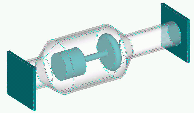
Step 3: Geometry read by Autodesk® CFD--the flow core has been created automatically, and is shown as the highlighted volume. There will now be five parts listed in the Material branch of the Design Study Bar: the pipe wall, the poppet, the two end caps, and the flow volume.
If there are objects inside of the flow volume, they will automatically be embedded into the flow volume. This means that it is not necessary to cut out submerged objects from their surrounding geometry.
If a internal core volume of a Design is changed, the material assignment will be lost from that part. Such a change would be the addition or removal of a part or features of a part that are inside the void. The reason for this is that core volumes are not created in the CAD tool, they are created by Autodesk® CFD when the geometry is read in. Because of this, there is no direct geometric link between the core volume and the original CAD model.
If it is not necessary to mesh a part (the pipe wall and poppet, for example), then suppress it from the mesh.
For example, in the preceding example, because the flow volume was created based on the solid geometry, the poppet is cut out from the flow volume, and fluid will not pass through this region even if the poppet is not meshed.
Submerged Objects and External Flows
Many analysis models are built with physical solids submerged in the flow. These often are part of a heat transfer analysis, and may carry a heat load.
The method for dealing with submerged objects is very simple: Place them in the desired location within the surrounding volume. It is not necessary to remove interferences or to cut an internal part from the surrounding volume. Autodesk® CFD will do this automatically. The following graphics illustrate this:
Step 1: An empty box representing the air in an electronics box.
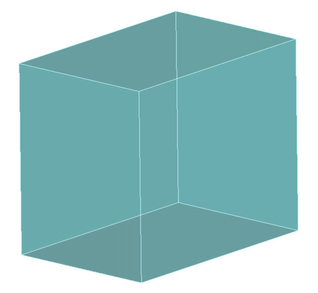
Step 2: Components are simply placed inside the box in the appropriate locations.
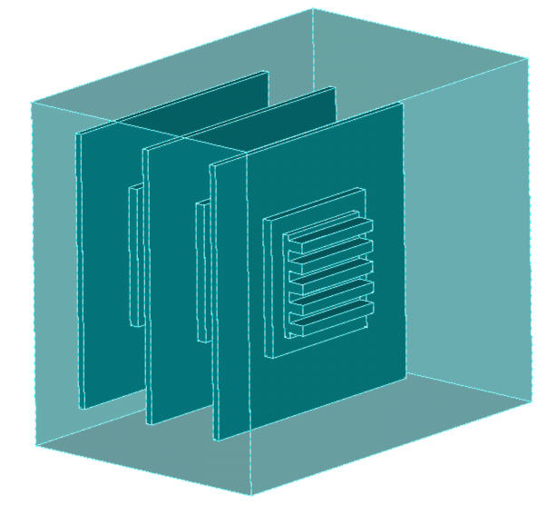
Step 3: As the model is read into Autodesk® CFD, the components are automatically cut from the air to remove all geometric interferences. Proper connectivity between all contacting parts is automatically ensured.
In our example, the air volume in the CAD system was only a box. As Autodesk® CFD reads the geometry, voids for the internal components were cut into the air. This is why the internal curves highlight when the air volume is selected.
This applies to both internal flows with submerged objects (examples include valves with poppets and electronic packages), and for external flows simulating the flow over a moving object. To include the obstruction as a meshable volume in the analysis model, simply place it in the surrounding volume at the desired location.
Note: Interferences are allowed in Parasolid and Acis-based CAD tool.
The External Volume Geometry tool can also be used to create a surrounding volume around a component.
Two Dimensional Geometry
Often two dimensional geometry is useful for simulating axisymmetric geometry or for simply an initial attempt at an analysis. A Parasolid or Acis surface in the XY plane is necessary for such an analysis.
Axisymmetric geometries must be constructed relative to the x or y axis properly. If the geometry is axisymmetric about the x axis, it cannot cross the x axis. If it is axisymmetric about the y axis, it cannot cross the y axis.
Note: we recommend that axisymmetric geometry be constructed in the first quadrant of the coordinate axis.
Part Names
Part names assigned in Parasolid- and Acis-based CAD tools appear in the Design Study Bar.
The naming convention of a part is based on the parent assembly and parts that surround it. For example, a part called small-chip is a member of a sub-assembly called left-board_asm. This part is immersed in a part called test-box. The part name in the Design Study Bar would be:
TEST-BOX_U_SMALL-CHIP-4@LEFT-BOARD_ASM
The “U” indicates that the part SMALL-CHIP is surrounded by the part TEST-BOX.
If a part is used multiple times in an assembly, an instance number is attached to the part name. In the example above, this part was the fourth instance of the part SMALL-CHIP.
If the geometry was not launched from a CAD tool, the part names are a combination of the CAD part name and any part that completely surrounds it. The name of the part listed above would be:
TEST-BOX_U_SMALL-CHIP^4
In some cases, the actual part name (without the surrounding part or assembly) is listed in the Design Study Bar. This is typically because the part is surrounded by an automatically-created flow volume.
Note that internal core parts that are created by Autodesk® CFD are assigned the generic name volume. This is because such parts were not created in the native CAD tool, and hence did not have a name. Also, the name of internal core parts are not used within the names of other parts they completely surround.