The tutorial starts with an Adaptive Clearing strategy to clear the elliptical shaped pocket.
- On the ribbon, click
CAM tab
 3D Milling panel
 Adaptive
 .
.
 Tool tab
- On the Tool tab, click the
 button and select the tool #12 - Ø8 R1 mm bullnose from the Sample Libraries > Tutorial library.
 - Click
 to close the Tool Library dialog.
 Geometry tab
Next, set the tool orientation and origin on the slanted face of the part.
- Click the Geometry tab.
- Enable the Tool Orientation check box to expand this group.
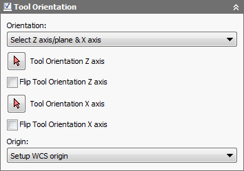
- Choose Select Z axis/plane & X axis from the Orientation: drop-down menu.
- Make sure the Tool Orientation Z axis button is active and select the slanted face as shown in the following image:
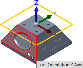
The slanted face of the part determines the new tool orientation
- It is now necessary to specify the direction of the X axis. Make sure that the Tool Orientation X axis button is active and select the horizontal edge of the part as shown below:

- The XYZ orientation of the tool is now correct, but the origin must be redefined. To do so, choose Selected point from the Origin: drop-down menu.
- Make sure the Tool Orientation origin button is active and select the point at the lower left of the part as shown below:
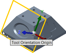

The new tool orientation and origin is now complete
- For the machining boundary, choose Selection from the Machining boundary: drop-down menu at the top of the dialog box.
- Make sure that the Machining boundary selection arrow is active and, in the graphics window, click on the outer elliptical edge of the pocket to select it.
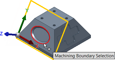
- Next, select Tool center on boundary from the Tool containment: drop down menu.
Now that the tool is in the correct orientation, the geometry can be selected.
Start the Calculation
- Click
 at the bottom of the Operation dialog box, or right-click in the graphics window and select OK from the marking menu, to automatically start calculating the toolpath.
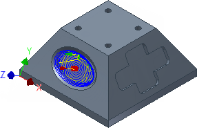
The toolpath is now calculated and a preview appears in the graphics window.
Continue to To Clear Using 3D Pocket...