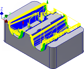
This operation uses the 3D Contour finishing strategy to finish the steep areas of the part.
- On the ribbon, click
CAM tab
 3D Milling panel
 Contour
 .
.
 Tool tab
- On the Tool tab, click the
 button.
 - From the Sample Libraries > Tutorial tool library, select tool #21 - Ø6 mm ball.
- Click
 to close the Tool Library dialog.
 Geometry tab
- Click the Geometry tab.
- From the Tool containment: drop-down menu, select Tool center on boundary.
- Change Additional offset: to: 1 mm
- Enable the Slope check box.
- Set From slope angle: to: 30 deg
 Passes tab
- Click the Passes tab.
- Change Maximum stepdown: to: 0.3 mm
- Disable the Flat area detection check box.
 Linking tab
- Click the Linking tab.
- From the Retraction policy: drop-down menu, select Minimum retraction.
- Change Safe distance: to: 5 mm
- Set Maximum stay-down distance: to: 8 mm
Start the Calculation
- Click
 at the bottom of the Operation dialog box, or right-click in the graphics window and select OK from the marking menu, to automatically start calculating the toolpath.
The toolpath is now calculated and a preview appears in the graphics window.

Continue to To Machine Using Parallel Finishing...