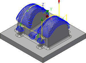
Next, create a constant Scallop toolpath on the shallow areas of the boss.
- On the ribbon, click
CAM tab
 3D Milling panel
 Scallop
 .
.
 Tool tab
The previous tool #20 - Ø10 mm ball should still be selected. Leave all other settings on this tab unchanged.
 Geometry tab
We want to confine the machining to shallow areas with this operation. This can be achieved by limiting the slope range.
- Click the Geometry tab.
- Enable the Slope check box.
- Change From slope angle: to: 0 deg
- Change To slope angle: to: 65 deg
- Enable the Avoid/Touch Surfaces check box.
- Activate the Avoid/touch surfaces button and select the flat face at the base of the part:

The set slope angle also includes the flat face at the base of the part, but this is finished later with 0 stock to leave using a Horizontal finishing strategy.
To avoid machining the flat base of the part we can select it as an avoid surface. To learn more, please refer to the Inventor CAM Help topic: About Avoid Surfaces.
 Passes tab
- Click the Passes tab.
- Set Tolerance: to: 0.02 mm
- Set Stepover: to: 1 mm
- Enable the Stock to Leave check box. Once again, use the default values of 0.1 mm.
Start the Calculation
- Click
 at the bottom of the Operation dialog box, or right-click in the graphics window and select OK from the marking menu, to automatically start calculating the toolpath.
The toolpath is now calculated and a preview appears in the graphics window.

Continue to To Use Scallop for a Finishing Operation...