You can use front, side, and top views from drawings, sketches, or photographs to help visualize your 3D model in Maya, much like an architect or engineer creates their designs from the plan and elevation views of a blueprint.
You can import 2D images into your orthographic camera views as image planes. An image plane is a 2D object (plane) that places an image file in the scene view. By default, an image plane only appears in the camera to which the image plane is connected. Image planes are also used to create backgrounds and environments when rendering.
When you load an image into an image plane, it appears in your selected orthographic view at the origin along an axis that is perpendicular to the selected orthographic view. You can refer to the image in the orthographic view to define the silhouette and character lines of your model. You can move the image plane, change its transparency, or turn it off.
For this lesson you load two images into image planes in the front and side orthographic views of your scene. You’ll refer to them frequently while you model the helmet.
To load reference images into the front and side orthographic views
- In the
Toolbox, click the
Four View shortcut from the
Layout Shortcuts bar.

The perspective view is located in the top right corner and the other views show your scene from the top, front, and side.
- In the front view panel menu, select View > Image Plane > Import Image.
- In the browser that appears, select the image file named
HelmetFront.jpg from the
sourceimages folder, and click
Open.
This image can be found in the GettingStarted2020LessonData directory that you set as your Maya project:
GettingStarted2020LessonData/PolygonModeling/sourceimages
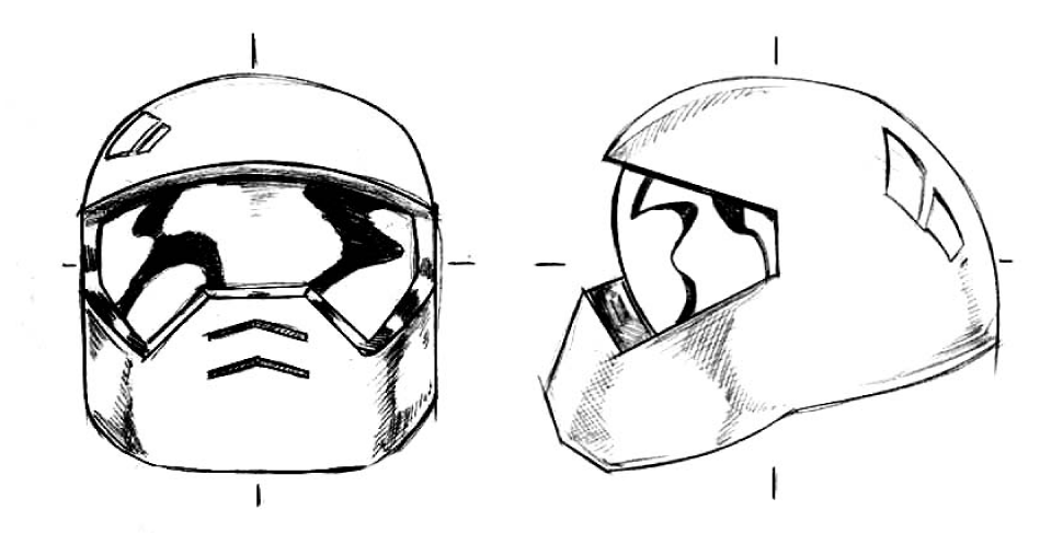
HelmetFront.jpg appears in the front view and depicts a drawing of the helmet.
- In the side view panel menu, select View > Image Plane > Import Image.
- Select the image file named
HelmetSide.jpg and click
Open.
HelmetSide.jpg appears in the side view.
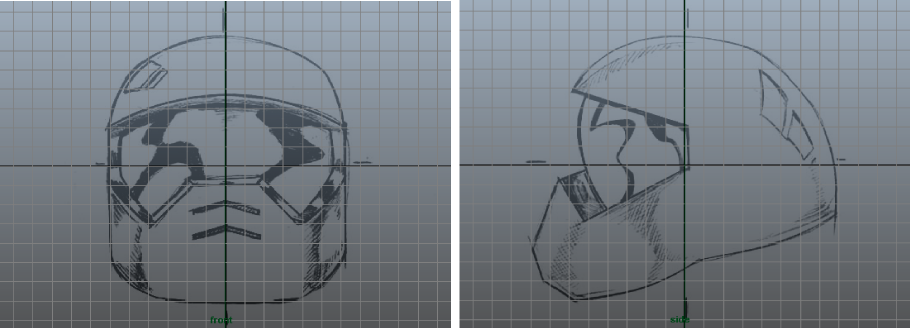
Note:The front and side images for this lesson were created so that the two views are aligned and the height of each image is identical. When you import them as image planes, they appear at the same scale. These are important considerations when you construct your own reference images in the future. Otherwise, your reference images may not align or may be at different scales between the two orthographic views.
By referring to the image planes in the orthographic views as you work, you can correlate how a feature in one view, appears in another. While a top view reference image is useful in many cases, it isn’t critical for this lesson.
The image planes can be set so they appear partially transparent to allow you to work with the polygonal components more easily. To do this you’ll select the front and side orthographic cameras and modify the transparency of the images.
To modify the transparency of the reference images
- Select the front reference image.
- Display the
Attribute Editor.
The Attribute Editor displays the attributes for the front reference image.
- Click the imagePlaneShape1 tab to select the image plane shape node.
-
Set the
Alpha Gain attribute to a value of 0.25.
The image appears partially transparent.
- In the side view panel menu, select the side reference image and change the
Alpha Gain attribute for the side view image plane exactly as you changed the front view image plane.
 Tip:
Tip:You can change the Alpha Gain at any time if you want the image planes to appear more or less transparent.
You can also set the reference images to only appear in the front and side cameras.
- Select the front reference image.
- In the Attribute Editor, under Image Plane Attributes, change Display to looking through camera front.
- Select the side reference image.
- Change display to looking through camera side.