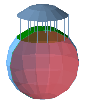
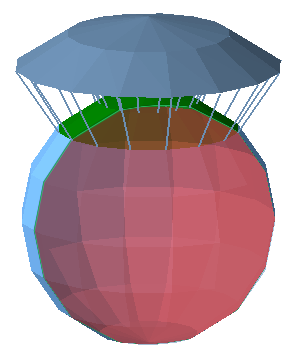
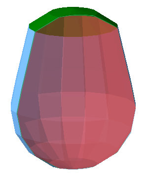
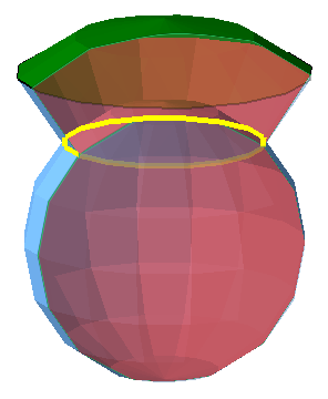
Transpose surfaces, and adjust the surrounding, or extend it with new triangles as needed
General Workflow
- Select the triangles or surfaces to extrude.
- From the menu, choose

 Extrude Surfaces.
- Choose the extrusion type.
- Adjust direction and distance as needed
- Click Apply to complete the extrusion.
Extrusion reference
Extrusion types
- Normal extrusion keeps the selected triangles and their sizes intact and shifts the nodes equally along parallel lines.
- 3D extrusion transposes surfaces along vertex normals (the average of the verticals on the triangles surrounding a common node), making extruded surfaces wholly thicker or thinner
Alignment help (Normal extrusion only)
- Hold the Shift key while moving the surface to lock the extrusion distance and only adjust the direction.
- Hold the Ctrl key while moving the surface to lock the direction and only adjust the extrusion distance.
- Double-click any triangle on the part to align the extruded surface parallel to the clicked triangle.
- Double-click the triangle again to invert the extrusion by 180 °.
- The same behavior occurs when you double-click on an edge of the part.
Extrusion variants
- Real Extrusion: Creates new triangles to create the extrusion
- Move Points: Moves the points of the selected triangles, rather than creating new triangles.
- Thickening (3D extrusion only): Performs a real extrusion and also generates an inverted copy of the original unextruded shell or triangle selection.
Note: If the original selection involved only a section instead of an entire shell, the new shell will technically be invalid and you will need to resolve the non-two-manifoldness between the triangles at the seam.

3D extrusion modifiers
- Smooth considers the extrusion direction of the surrounding triangles. This helps to limit the contrast between the extruded surface and the adjacent surfaces.
- Improved takes the size of the selected triangles into account. The extrusion direction is determined primarily by the larger triangles.
Both modifiers only apply a small correction.
Normal direction options
- Specify numerical values for the three cardinal axes. Their relative values are normalized into a vector which produces the actual direction.
- Estimate direction: By considering the direction of the verticals (normals) over all selected triangles, weighted by their sizes, a common direction is determined.
3D direction options
- X, Y, Z, By Face Normal: These are toggled switches. By using them, you lock the direction in which the extrusion must not happen. Click the button to enable the lock, click it again (or click another one) to disable the lock. Only one switch can be locked at any time.
- After clicking By Face Normal, you may click one triangle on the part to determine the direction of locking from the chosen triangle. Click the button again to remove the lock.