Read more about meshes and requirements for additive manufacturing
Triangle mesh files are typically lists of some form or another, containing corner point coordinates for the triangles. Adjacent triangles may use common corner points and share the same edges which results in a continuous triangle mesh.
However, many mesh file formats (like STL) do not contain any topological information about the bodies they represent. If a CAD file is imported with errors, very little information remains to consistently reconstruct missing or faulty surface automatically. Use Netfabb to detect and repair such damage and to create faultless meshes without holes, deformations or intersections. These meshes can then be converted into slice files ready for additive manufacturing.
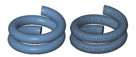
A parametric surface and its triangulated representation
Although CAD formats have advantages, a variety of applications needs a surface representation consisting of flat triangles. These are:
- Rapid prototyping and additive manufacturing
- Accelerated rendering in multimedia applications
- Solving partial differential equations to simulate mechanical and thermal loads
- Computer Aided Design (CAD)
A good triangle mesh that can be used for 3D printing must be valid, closed, oriented and generally free from self-intersections.
Jump to:
Validity
Two edges of adjacent triangles which lie on top of each other are only regarded as one edge when they have equal end points. Thus, the simple mesh below consists of two triangles and has exactly five edges: four border edges and one interior edge. Border edges belong to only one triangle, while interior edges connect two triangles.
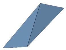
A simple mesh with 5 edges: four border edges and one interior edge.
A mesh is only regarded as valid when interior edges have the same corner points for both adjacent triangles. Only then, all neighboring triangles are connected by a whole interior edge. No neighboring triangles are split and a smooth topology is created.
This validity is an essential property of most calculations. If two edges have only one common corner point, they are defined as two border edges, even if they are on top of each other.
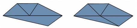
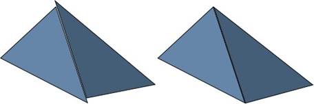
An invalid triangulation (left) compared to a valid triangulation (right).
Closedness
Parts can only be used for 3D printing when their surface is closed. This means that there are no holes and no border edges. Every edge must be attached to exactly two triangles and all neighboring triangles have to share an interior edge. Closedness may separate a mesh into several components called shells.
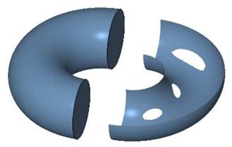
A closed surface (left) and a surface with holes (right)
Two disconnected (left) and two connected triangles (right)
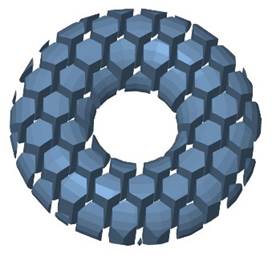
A mesh consisting of 60 disjoint shells.
Orientability
For the conversion of triangle meshes into slice data ready for 3D printing, it is vital that the parts are oriented correctly. The orientation defines the outside and the inside of a part.
The orientation of a part is determined by the orientation of all triangles. The orientation of a triangle is in turn determined by the order in which the corner points are defined. If the orientations of all neighboring triangles conform to each other and there are no flipped triangles, a closed shell separates outside from inside. But if there are flipped triangles, this might not be possible. Thus, even closed parts can be faulty.
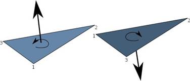
The orientation of a triangle is determined by the order of its points.
Self-Intersections
The surface of a solid body must not contain any self-intersections. These occur whenever triangles or surfaces of one part cut through each other. For many applications, self-intersections are undesired as they can cause calculations and slice and toolpath generation to produce incorrect results..
For most additive fabrication processes, three-dimensional data must be converted into 2.5-dimensional slice data. Here, self-intersections in the original data result in self-intersection in the slices. These can cause constructional failures or instabilities. Therefore, it is essential to remove self-intersections during the preparation of files.
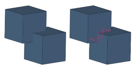
Self-Intersection: The two cubic shells cutting through each other
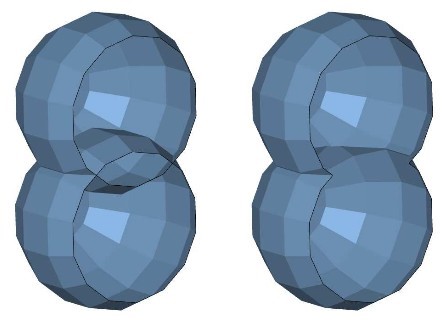
Left: A mesh consisting of two shells with self-intersection. Right: A mesh consisting of one, non-intersecting shell.