Create additional nodes to filter situations based on criteria such as zones, sections or angles.
Filter by zone type
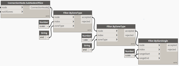
The next Dynamo node to add to the script is Filter.ByZoneType. This node takes as an input a connection node (or a list of connection nodes), an index corresponding to the structure data element in the connection node and a zone type, which can be end or body (currently specified as a case insensitive string). As output, the Dynamo node shows the connection nodes that meet the criteria and the ones that do not.
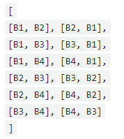
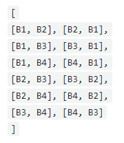
In this example, to check if the connection node between B1 and B2 is of type end-to-end, firstly, verify that the zone type is end for the first element (index = 0) in the node. Since all elements (B1, B2, B3, B4) have the end zone type, the filter passes for all of the sub nodes.
| Input | Output
Accepted |
Output
Rejected |
|---|---|---|
 |
 |
[ ] |

Next, add a second Dynamo node to check that the zone type for the second element (index = 1) is also end.

All the connection sub nodes meet the criteria.
| Input | Output
Accepted |
Output
Rejected |
|---|---|---|
 |
 |
[ ] |
Filter by slant angle
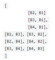
The next filter to add to the script is Filter.BySlantAngle. The slant angle is the angle formed by the axis of the structure data element and the vertical axis. The slant angle is complementary to the slope angle. This filter is required to check that the first element is vertical. This Dynamo node takes as input a connection node or a list of connection nodes, the index of the structural element from the connection node to be checked, the start and the end of the slant angle range (0-90°), in degrees.
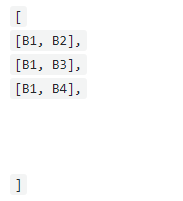
In this example, it is checked that the first element (index = 0) in the connection node has the slant angle between 0 and 0 degrees, for it to be vertical.
| Input | Output
Accepted |
Output
Rejected |
|---|---|---|
 |
 |
 |
Filter by slope angle
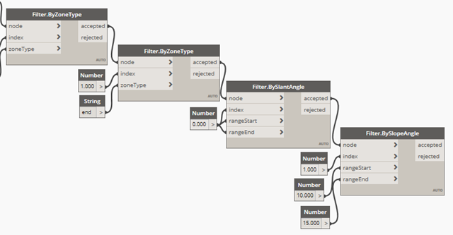
The next filter to add to the script is Filter.BySlopeAngle. The slope angle is the angle formed by the axis of the structure data element and the horizontal plane. The slope angle is complementary to the slant angle. This filter is required to check that the second element has the slope between 10 and 15 degrees. The Dynamo node takes as input a connection node or a list of connection nodes, the index of the structural element from the connection node to be checked, the start and the end of the slope angle range (0-90°), in degrees.
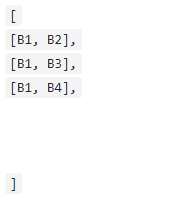
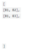
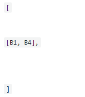
In this example, it is checked that the second element (index = 1) in the connection node has the slope angle between 0 (rangeStart) and 15 (rangeEnd) degrees.
| Input | Output
Accepted |
Output
Rejected |
|---|---|---|
 |
 |
 |
Filter by angle between axes
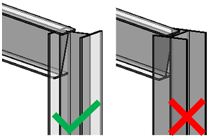
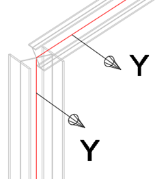
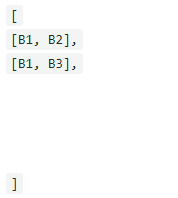
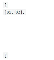
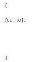
Add the Filter.ByAngleBetweenAxes Dynamo node. The node takes as input a connection node or a list of connection nodes, the indexes of the structural elements from the connection node to be checked, the two axes to be checked (x, y, or z), the start and the end of the slope angle range (0-90°), in degrees.
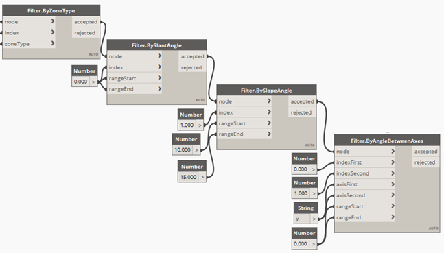
Since the web of B3 is not parallel to the web of B1 B1, the [B1, B3] connection node fails to meet this filter criteria.
| Input | Output
Accepted |
Output
Rejected |
|---|---|---|
 |
 |
 |
Filter by section shape
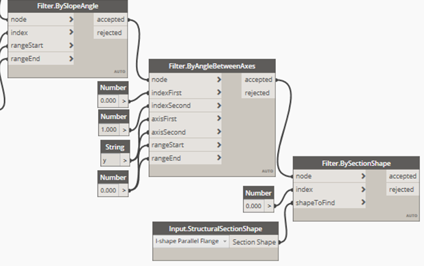
You can use the Filter.BySectionShape Dynamo node to check the section shape of the profile used for the structure data element. You can find the section shape in the Revit Type properties dialog, under Structural, in the type Parameters list.
| Input | Output
Accepted |
Output
Rejected |
|---|---|---|
 |
 |
[ ] |
Filter by section type
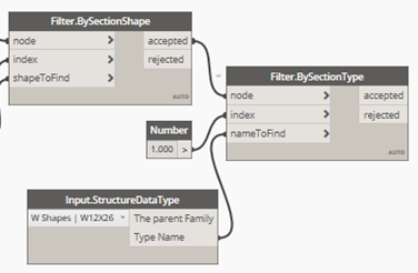
You can usethe Filter.BySectionType Dynamo node to check the section type name of the structure data element.
The Dynamo node takes as input a connection node or a list of connection nodes, the index of the structural element from the connection node to be checked, the section type name, for which an additional Dynamo node called Input.StructuralDataTypes must be used.
| Input | Output
Accepted |
Output
Rejected |
|---|---|---|
 |
 |
[ ] |
Filter by section profile
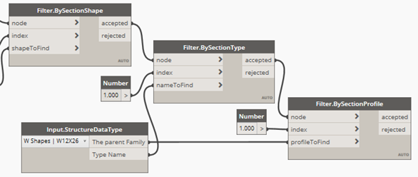
You can use the Filter.BySectionProfile Dynamo node to check the section profile used for the structure data element.
| Input | Output
Accepted |
Output
Rejected |
|---|---|---|
 |
 |
[ ] |
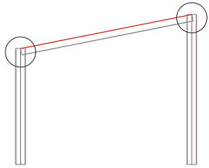
Filter by angle between beams
The filter by angle between axes checks the angle between X, Y and Z, and receives input between 0-90°.
The filter by angle between beams is a particular case of that filter, where both axes are X.
Filter by vertical position
The Filter.ByVerticalPosition Dynamo node takes as input a connection node (or a list of nodes), the index of the structural element from the connection node to be checked, and a position string, which can be "Top" or "Bottom" - based on the desired filtering position. For example, this filter is useful for always placing base plate connections at the bottom of the column.
Filter by member end forces
The Filter.ByMemberEndForces Dynamo node takes as input a connection node (or a list of nodes), the index of the structural element from the connection node to be checked, the type of result (Fx, Fy, Fz, Mx, My, Mz - you can use the Input.ResultTypes node), the start and the end of the range of forces (for which the Revit units are considered). This Dynamo node can be used in order to place connections based on the values of the forces at the end of the framing element, for the forces defined in the Revit Member End Forces dialog.
Filter by analysis results
The Dynamo node takes as input a connection node (or a list of connection nodes), the index of the structural element from the connection node to be checked, the type of result (Fx, Fy, Fz, Mx, My, Mz - you can use the Input.ResultTypes node), the analysis result package together with the desired load case or combination or envelope (requires the Input.AnalysisResults node), and the start and the end of the range of forces (for which the Revit units are considered). You can use this node to place connections based on the values of the forces at the end of the framing element, for the analysis results stored in the Structural Analysis Toolkit.
Next step: Add Connections to the Dynamo Script