Review an example of creating a steel connections for Dynamo script that scans the model for connection nodes of two framing elements.
Note: A set of steel connections sample scripts is also available in the Dynamo
installed packages. You can use these sample scripts as starting points for your custom scripts.
The connection nodes should meet the following criteria:
- The two elements meet end-to-end.
- The first element has a slant angle of 0 degrees.
- The second element has a slope angle between 10 and 15 degrees.
- The webs of the two framing elements are parallel.
- The first element has an I shape-Parallel Flange section shape.
- The second element has a W Shapes family and a W12X26 type.
Whenever all these conditions are met, the script will place the Knee of frame, bolted, with haunch connection. The connection will have the I shape-Parallel Flange section as the primary input element and the W Shapes family, W12X26 type as the secondary input element.
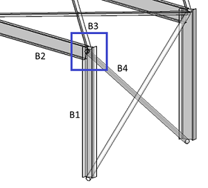
The connection node marked in the following image is a connection node of four elements. Place the Knee of frame, bolted, with haunch between B1 and B2, with B1 as the main element and B2 as the secondary element.


Note that:
- The slope angle for B2 is 11 degrees.
- B1 is vertical.
- The web of B1 is parallel to the web of B2.
- B1 and B2 meet end-to-end.
- The webs of B1 and B2 are parallel.
- B2 has a W Shapes family and a W12X26 type.
First step: Select and Group the Connection Input Elements