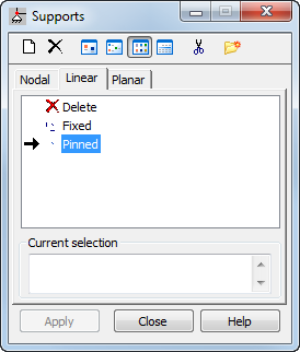
Learn how to set a linear pinned support.
- Continue working in your project, or open the project Plate_Properties.rtd.
Note: The Tutorial files are located in C:\ProgramData\Autodesk\Examples\Tutorials.
- Click
 (Geometry
  Supports).
The Supports dialog opens.
- Go to the Linear tab, double-click on Pinned support.
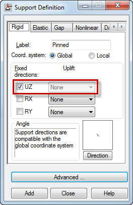
 The Support Definition dialog opens.Tip: You can use the Support Definition dialog to see the defined support properties, create supports, or modify existing ones.
 - In the Rigid tab, ensure that Fixed directions UZ is selected.

- Click Close.
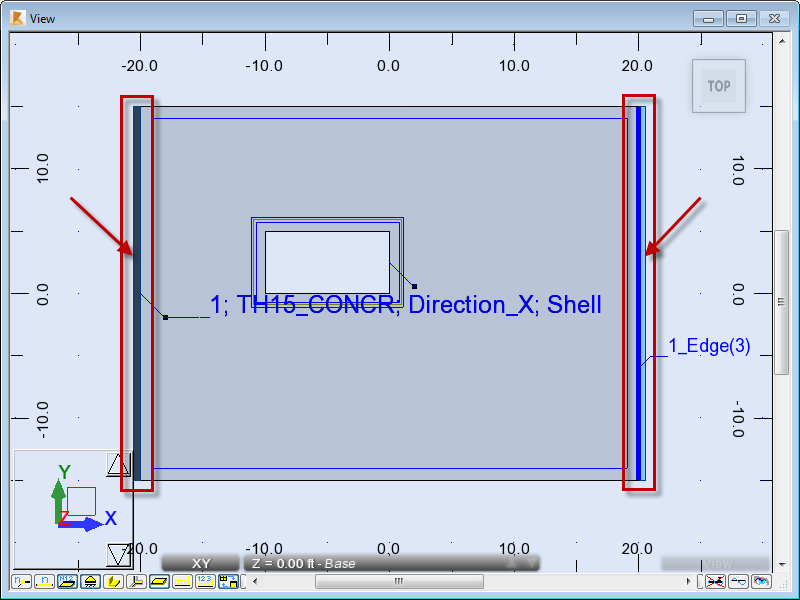
- In the Supports dialog, click inside the Current selection box, and then in the drawing area click on the edge labeled 1_Edge(1).
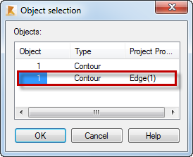
The Object selection dialog opens.
Tip: The name of the edge displays if you move the cursor over the selected edge. To display all the edge names, click View Display
  Panels/FE
  Numbers and labels of edges.
 - Select the Edge(1) edge.

- Click OK.
1_EDGE(1) appears in the Current selection box.
- Click Apply.
- Repeat steps 6 to 9 to select the 1_Edge(3) edge.
 Alternatively you can select the edges in two other ways:
- Method 1: In the drawing area select the edges without clicking in the Current selection box in the Support dialog.
- Method 2: Enter the name of the edges in the Current selection box: 1_Edge(1), 1_Edge(3), and then click Apply in the Supports dialog.
- Close the Supports dialog.
- Save the project as Plate_Supports.rtd.