Learn how to define types and values of surface loads for particular load cases.
- Continue working in your project, or open the project Plate_Defined_Loads.rtd.
Note: The Tutorial files are located in C:\ProgramData\Autodesk\Examples\Tutorials.
- In the Cases Selection box of the Selection toolbar, expand the Cases drop-down menu and select 2: LL1.

- Click
 (Loads
  Load Definition).
The Load Definition dialog opens.
- Go to the Surface tab, and click
 (Uniform Planar Load).

The Uniform Planar Load dialog opens.
- Enter -0.07 in the PZ: box, and then click Add.
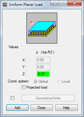
- Place the cursor in the Apply to box, and type 1 to indicate the plate on which you want to apply a uniform planar load.
Alternatively, you can select the plate graphically. To do it, go to the drawing area, and then the
 icon appears which allows you to select the plate.
 - Click Apply.
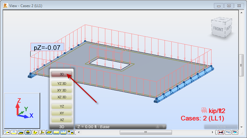
The LL1 load appears in the drawing area.
- Click
 (Load value descriptions) at the bottom of the drawing area to display the descriptions of loads values.
 - At the bottom of the drawing area, expand the list of views, and then select the 3D view.
- In the Cases Selection box of the Selection toolbar, expand the Cases drop-down menu and select 3: LL2.

- Go to the Load Definition dialog, and then in the Surface tab, click
 (Linear Load 2P).
The Linear Load 2P dialog opens.
- In the Linear Load 2P dialog set the following parameters:
- P1=P2: - 0.20,
- Coordinates: A: (5.00,-15.00) and B: (5.00, 15.00).
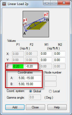
- Click Add.
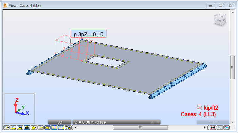
The LL2 load appears in the drawing area.

- In the Cases Selection box of the Selection toolbar, expand the Cases drop-down menu and select 4: LL3.

- Go to the Load Definition dialog, and then in the Surface tab, click
 (Uniform Planar Load on Contour).
The Uniform Planar Load on Contour dialog opens.
- Enter - 0.10 in the PZ: box.
- Click Contour definition.
The Contour definition area expands.
- To create the contour for the load, enter the following point coordinates:
- (-20.00, 0.00), click Add,
- (-10.00, 0.00), click Add,
- (-10.00, 5.00), click Add,
- (-20.00, 5.00), click Add.
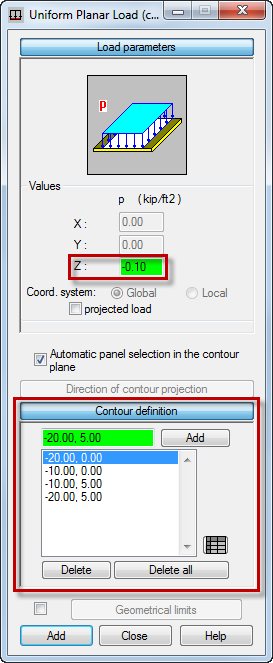
- Click Add.
The LL3 load appears in the drawing area.
- Close the Load Definition dialog.
- Click Loads
 Load Table to open the Loads table.
Alternatively, click
 (Tables) in the Structure Model toolbar on the right side of the program to open the Tables: Data and Results dialog. Then select Loads and click OK.
 The Loads table opens.
- Ensure that you have the same properties of loads as shown below:
 Tip: You can use the Loads table to modify the defined loads. For example, you can change the loads types, the list of elements where loads are applied and the values of these loads. You can also use this table to add new loads to the structure.
 - Click the
 icon in the upper right corner of the table to close the Loads table.
- Click in the drawing area to deselect the panel.
- Save the project as Plate_Applied_Loads.rtd.