Learn how to display the final reinforcement in the view and in tabular form.
- Continue working in your project or open the project Plate_Provided_Reinforcement_Deflection.rtd.
Note: The Tutorial files are located in C:\ProgramData\Autodesk\Examples\Tutorials.
- In the Standard toolbar, expand the Layouts drop-down menu and select Slab - reinforcement as shown below:
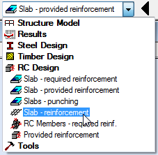
The layout is divided in four parts: RC Component Inspector, Slab - Reinforcement view (top and bottom), Reinforcing Bars dialog, and Reinforcement table.
- Click
 (Analysis
  Calculations).
The Calculations dialog opens.
- Click Calculate.
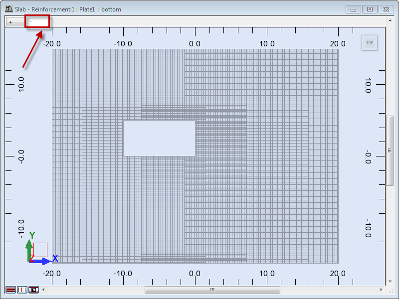
The top reinforcement displays in the + tab.
- Go to the Slab - Reinforcement view and click the
 tab to display the bottom reinforcement.
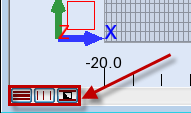
 Tip: To present the selected type of reinforcement (main, structural, or opening reinforcement), click one of the tabs highlighted below. The tabs are located in the lower left corner of the drawing area. By default, the program presents all types of reinforcement.
- Go to the Reinforcement table and select row 12.
The row is highlighted in black and the selected reinforcement displays in red in the view.
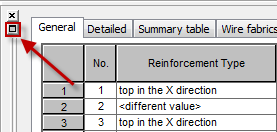
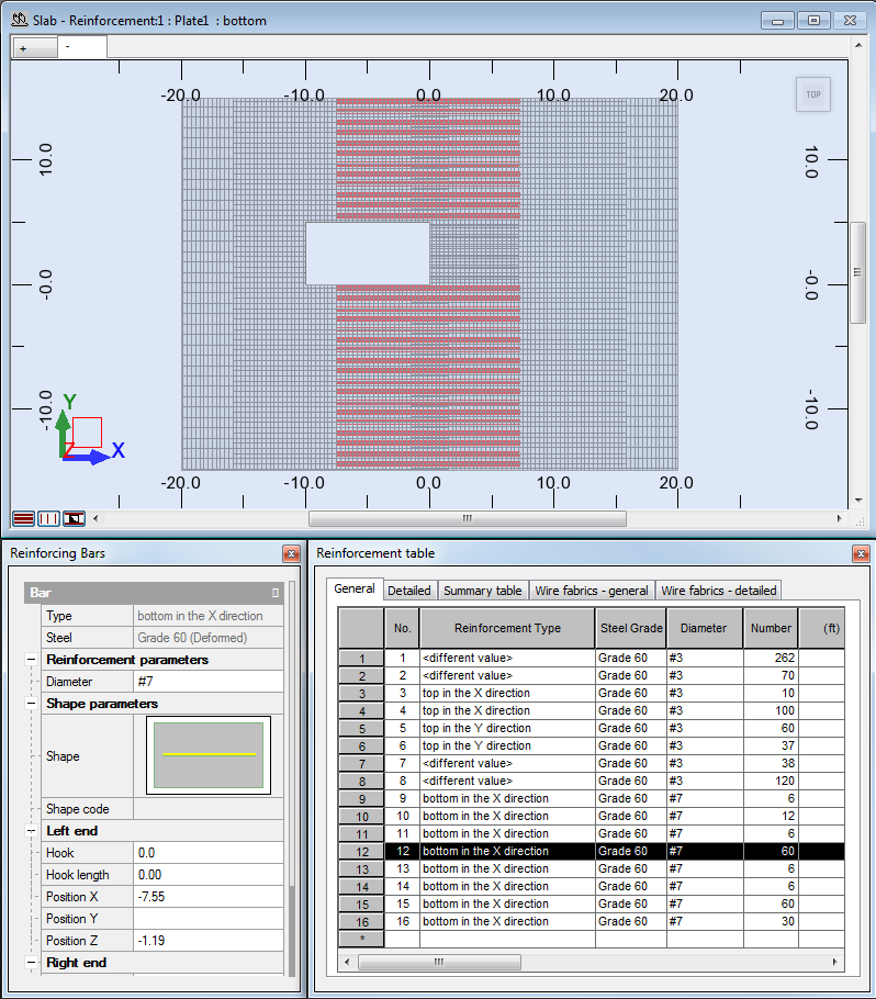 Tip: You can undock the Reinforcement table or Reinforcing Bars dialog by clicking the icon as shown below. You can also close them and open them again if necessary, by clicking Reinforcement
 Reinforcement table (or Bar properties).
- Click
 (Results
  Drawings).
The Final Drawings layout opens. The layout is divided in two parts: RC Component Inspector and Drawing view.
- Click View
 Next Drawing, or click the right arrow to display the next drawing.

- The Bottom slab reinforcement drawing appears in the Drawing view.
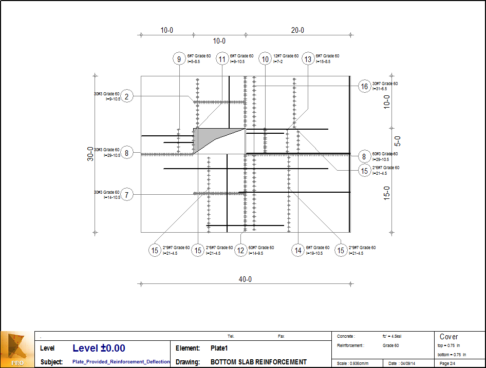 Tip: To edit/modify drawing elements and their contents, click
 (View
(View  Drawings Components). For more information, see Final Drawings - Description.
 - Save the project as Plate_Provided_Reinforcement_END.rtd.
Click here to go to the Summary.