When using the Profile Group Parameters dialog for a Pocket Mill strategy, the following settings are available:
Style — Select the style you want to use to machine the pocket:
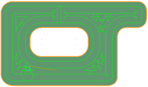
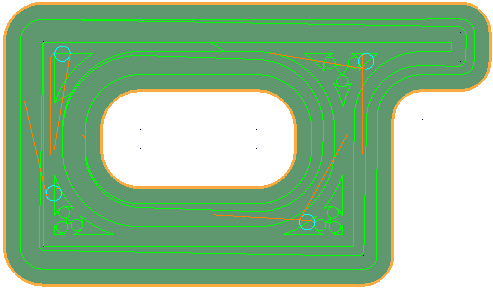
- Spiral — Select if you want the tool to start in the center and move outwards along a spiral toolpath until it reaches the boundaries. Spiral pocketing supports islands and the nesting of islands and pockets.
- Linear — Select if you want the tool to start at the boundaries and move towards the center, zig-zagging from side to side, until it reaches the opposite side. Linear pocketing supports islands and the nesting of islands and pockets. See also the description of the Angle field for details of how to specify an angle for a linear pocket.
Optional Pass — Select an option to specify whether you want a clean-up pass to be performed for this toolpath. As PartMaker automatically detects where material is left and generates clearance toolpaths accordingly, it is unlikely that a clean-up pass will be required. However, the option has been retained for compatibility with PartMaker v2013 and earlier.
- None — Select to specify that no clean-up pass is performed.
- All Boundaries — Select to perform a clean-up pass for all islands and boundaries.
- Islands Only — Select to perform a clean-up pass for islands only.
Toolpath Direction — Select an option to specify the direction of the toolpath. This option is applicable only for Spiral pockets.
- Follow Profile — Select to create a toolpath parallel to the direction of the profile that comprises the pocket’s outer boundary. This option provides compatibility for PartMaker versions prior to v2010 when Toolpath Direction was not programmable.
- Climb Mill — Select to create a toolpath that uses climb milling, which means the tool is on the left of the machined edge when viewed in the direction of tool travel. This option simplifies the programming of a pocket’s outer boundary, as it removes the need to consider the milling style required when creating the pocket outline.
- Conventional Mill — Select to create a toolpath using only conventional or 'upcut' milling, which means the tool is on the right of the machined edge when viewed in the direction of tool travel. This option simplifies the programming of a pocket’s outer boundary, as it removes the need to consider the milling style required when creating the pocket outline.
Z_Surf (S) — Enter the signed distance from the zero reference point to the part surface.
Z_Depth (D) — Enter the depth of the operation to be performed.
Z_Rapid (R) — Enter the distance between the bottom tip of the tool and the part surface when a tool performs rapid moves.
Z_Clear (Cl) — Enter the distance between the bottom tip of the tool and the part surface when a tool starts feeding into the part.
Bottom Finish (b) — Enter the amount of material left on the bottom for finishing if the Finishing option is selected.
Wall Finish (w) — Enter the amount of material left on the wall for finishing if the Finishing option is selected.
Angle (a) — Enter the angle of the X axis formed by the toolpath in a linear pocket.
Linear Extension (L) — Enter the length of the linear extension that is added from the center of the innermost pass to the start point of the innermost pass, as a percentage of the tool diameter. If you do not require a linear extension, enter 0. This option is available only for spiral pockets where Center Entry is not selected.
Out to In — Select this option if you want the toolpath to start from the outer edge of a pocket, and work inwards, rather than starting from the inside and working outwards. This option is applicable only to spiral pockets where Advanced Milling Toolpath is not selected.
Minimize Air Moves — Use this option to control how the toolpath offsets and minimizes air moves:
- When this option is selected, the toolpath offsets all spans and minimizes air moves.
This produces a toolpath which minimizes the number of lifts and works extremely well for soft materials.
Each area is machined with one plunge at the start of the toolpath. This works well if cut direction is not important, as it is difficult to maintain cut direction if you are not allowed to lift the tool.
- When this option is deselected, the toolpath offsets the spans in contact with the model (which does not minimize air moves).
This produces a toolpath which:- Maintains constant tool load and chip production.
- Maintains cut direction.
- Avoids machining small or thin walled upstands.
- Minimizes full-width cuts.
This option increases the number of lifts.
Center Entry — Select so that PartMaker adds a linear extension from the center of the innermost pass to the start point of the innermost pass. This option is applicable only to spiral pockets. It is not available if Out to In is selected.
Operations information
- Roughing — Select this option to include a roughing pass operation.
- Finishing — Select this option to include the finishing pass operation.
- Diam (d) — Enter the diameter of the tool used to perform the selected operations, for example Roughing and Finishing operations.
- Tool ID
— Enter the ID of the selected tool. When you have saved the group, you can click the icon showing a representation of the tool (for example
 ) to display the
Edit Tool dialog to view, or modify, details of the tool.
) to display the
Edit Tool dialog to view, or modify, details of the tool.
- Width of Cut — Enter the width of the cut for the operation. This value can be calculated as a percentage of the diameter of the tool selected for the operation or specified as an absolute value, depending on the Width of Cut and Width of Cut Value settings on the Defaults for Milling dialog.
- Axial Step — Enter the axial step of the tool. By default, PartMaker uses the Axial Step value specified in the tool's properties in the Tools Data dialog. If the axial step is set to zero, the material is removed in a single axial step.
Advanced Milling Toolpath (legacy) — Select this option if you want PartMaker to use Advanced Milling options when calculating the toolpath for this profile group. When this option is selected, the following buttons are available:
- High Speed — Click to display the High Speed Machining dialog to set up options for high-speed machining. These include options for trochoidal milling, toolpath smoothing, profile smoothing and stroke transition.
- Rest Area — Click to display the Rest Area Machining dialog to set up options for rest area machining. Rest area machining enables you to machine only that area within the profile boundary which has not been machined by the previous toolpath.
- Sloped Walls — Click to display the Sloped Walls Machining Options dialog. Use this dialog to set options related to the machining of sloped walls.
- Advanced Tool Entry —Click to display the Advanced Tool Entry dialog. Use this dialog to specify how the tool plunges into the material at the beginning of a cut when using an Advanced Milling toolpath.
Polar Style Output — Select this option to specify whether the NC program is in polar format. This allows for Posts to explicitly support machining without polar interpolation activated in the NC code. This option is available only when using a Mill End, Polar Face window.
- When selected, the post will typically output X and Y positions with polar interpolation activated.
- When deselected, the Post will typically output Radius and C-angle positions without polar interpolation.
Lock Toolpath — Select this option to lock the toolpath. When a toolpath is locked, PartMaker does not recalculate it even if its settings on the Profile Group Parameters dialog change. Deselecting this option unlocks the toolpath.
Tool Entry — Click to display the Tool Entry dialog. This button is available only when the Advanced Milling Toolpath option is not selected.
Group Name — Enter a name for the profile group.
Select Tools — Click to display the Select Tool dialog, where you can select the tool to use for machining.
Extract Parameters From Solid — Select this option to extract geometric information from the imported solid model and use this information to complete some of the fields on this dialog. When you have selected this option, select surfaces on the solid model and then click Extract to extract the geometric information. Press the Shift key to select more than one surface at a time. Click Undo to revert any values on the dialog that have been calculated by extracting geometric data from the solid model back to their original values.