You can create items by selecting the features directly from the CAD model. This example demonstrates how to create inspection items for the two probed circles used in the alignment. The centre of the first circle is used to determine the origin of the alignment. The centre of the second circle is used to construct a line in Stage 5.
To create two probed circles:
- Select Home tab > Mouse Context panel > Wireframe Checker.
- Move the cursor to the edge of the circle, as shown below:
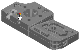
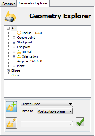
- When the circle is highlighted in yellow, click the left mouse button. The circle's nominals are displayed in the Geometry Explorer tab, for example:
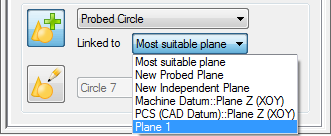
- In the Linked to list, select Plane 1 to associate the circle with the plane you created in Stage 2.
- Click Accept
 .
.The circle is added to the inspection sequence.
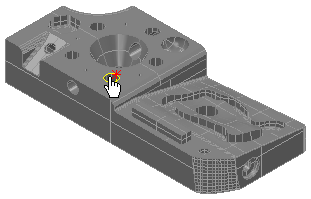
- Move the cursor to the edge of the second circle, as shown below, and repeat steps 3 to 5 to create a second circle item.
Notice the symbols shown alongside the items you have added to the inspection sequence.
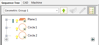
 indicates the item is unmeasured.
 indicates the item is displayed in the CAD view.
  indicates the item is used by other items in the sequence. You cannot delete a referenced item until you have deleted the items that use it.
 - Click the light-bulb symbol next to the plane item to hide it in the CAD view.