Triangular Element Connection
Description: Defines a triangular, isoparametric membrane-bending or plane strain plate element with vertex rotations.
Format:

Example:

| Field | Definition | Type | Default |
|---|---|---|---|
| EID | Element identification number. | Integer > 0 | Required |
| PID | Identification number of a PSHELL or PCOMP property entry. | Integer > 0 | Required |
| Gi | Grid point identification numbers of connection points. | Integer > 0, all unique | Required |
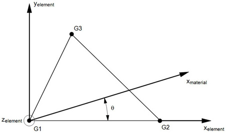
| THETA | Material property orientation angle in degrees. | Real | See Remark 5 |
| MCID | Material coordinate system identification number. | Integer ≥ 0 | See Remark 5 |
| Ti | Membrane thickness of element at G1, G2, and G3. | Real ≥ 0.0 | See Remark 6 |
Remarks:
- Element identification numbers must be unique with respect to all other element identification numbers.
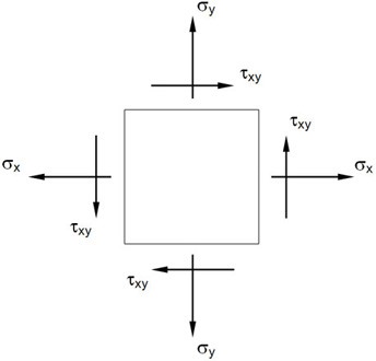
- Stresses are output in the surface coordinate system. (See the SURFACE command in Section 3, Case Control.)
- The rotational degrees of freedom at the connection points and normal to the element are active in the element formulation and must not be constrained unless at a boundary. If they are constrained then inaccurate results will be obtained.
- This element is less sensitive to initial distortion and Poisson's ratio than the CTRIA3 element and is more compatible with the CBAR and CQUADR elements which also have 6 degrees of freedom per node.
- If THETA/MCID is blank, field 5 of the PSHELL continuation entry will be used. If this field is also blank, then THETA = 0.0 is assumed when a non-isotropic material is referenced.
- If Ti in fields 4 through 7 of the continuation entry are blank, field 4 of the PSHELL entry will be used. This is the preferred way of specifying element thickness if the thickness does not vary over the element.

Figure 1. MCID Coordinate System Definition

Figure 2. CTRIAR Element Geometry and Coordinate System


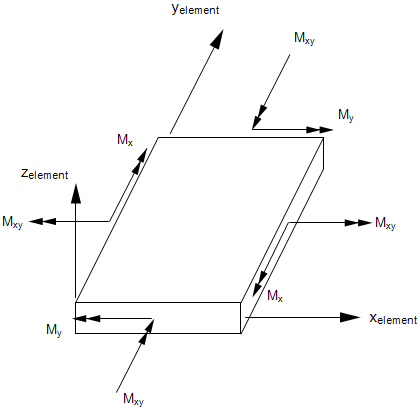
Figure 3. Forces and Moments in CTRIAR Elements

Figure 4. Stresses in CTRIAR Elements