The 'Buckling Model' option allows for setting buckling parameters for the designed column. It is available from:
- the toolbar by selecting the 'Buckling Model' icon
 or
or - the menu by selecting the RC element / Buckling Model command.
Once the option is selected, a dialog box shown below will appear on the screen.

The above dialog box is used to:
- select the column buckling model (buckling length) for the Y and Z directions (i.e. the buckling model in the directions that cause an increase of the My and Mz moments; the interpretation is illustrated in the drawing below):
Ly, Lz - column lengths: distances measured between idealized points, resulting from intersections of a column with other elements in a calculation model, are calculated based on elevation dimensions of the column and an adopted buckling model; NOTE: If a column was loaded from a Robot structure model, then a theoretical column length (i.e. node-to-node member length) is adopted.
Loy, Loz - design length of a column resulting from an adopted buckling model and a structure type (Loy = ky * Ly, Loz = kz * Lz)
- select the structure type containing the column (sway/non-sway),
- define the structure height (the parameter used in the EC2 code)
- exclude consideration of buckling in the selected direction; if the Direction Y or Z option is switched off, it means that in a given direction a column will be treated as a short one and additionally, the critical force (if it is calculated for a given code) will not be taken into account as the yield strength.
The program allows saving defined parameters of a buckling model in the form of a set of parameters, and then using it to ensure faster definition of a buckling model in successive structure elements. To save a parameter set (or modify the predefined Standard set), after setting selected model parameters the user should press the Save As button in the above dialog box and specify a name of a new set. A set will be added to the list of buckling models. To remove a set from the list, the user should select it on the available list and press the Delete button.
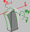
The interpretation of buckling directions (shown on the example of Direction Y)
The designation Direction Y corresponds to buckling in the direction that causes an increase of the My moment (about the Y axis), in other words, it refers to buckling of a column from the vertical plane XY. Thus for the direction Y the eccentricity in the direction of the Z axis is considered. It is illustrated schematically in the drawing below.

The dialog box consists of three main parts:
- Total Structure Height - field for setting the structure height. The default value is a four times the column height but it can be modified.If any of the column dimensions are changed, the default value will be change correspondingly. selection field (the same parameter for both directions: Y and Z)
- two fields: Direction Y and Direction Z.
The Direction Y and Direction Z fields belong to the same group of options - separately for the directions: Y and Z. The description of the option mechanism will be based on the Direction Y example. The icon corresponding to the buckling model for the direction Y is located on the left side of the field. Once this icon is selected, an additional dialog box will be opened and the selection of the required buckling model can be made (Selection of the buckling model). Once the Buckling Model dialog box is open the icon corresponds to the currently selected model. After changing the model to a new one, the Ly and Ly / Lo values will be set as default ones corresponding to the current column dimensions. If a value of the buckling length coefficient is entered manually, the icon representing a buckling model will be replaced by an icon indicating a user-specified value.