Follow the steps below to generate wind loads automatically.
- Click
Loads
 Wind loads simulation
 Generate Wind Loads.
The
Wind simulation dialog displays.
- Ensure that you are on the General tab of the Wind simulation dialog.
- In the
Wind direction group, select at least one direction for the wind.
Note: The wind direction is set according to the global coordinate system. By default, the X+ direction is selected.
- Specify the wind intensity and the ground level in the
Wind parameters group.
- Select if you want to specify the wind intensity by its velocity or by its pressure, and then enter a value for the selected parameter.
- Enter the ground level in the terrain level box.
Note: By default, the ground level is set to the lowest Z coordinate of the current model.
- Specify the elements for which you want to launch a wind simulation in the
Wind exposure group.
- Click inside the
Elements box, and then select the elements in the drawing area, or click
All to select them all.
Note: By default all the elements are considered during the simulation.
- Leave the Openings in panel closed for the wind flow option selected, unless you want to allow the wind to flow through the model.
- Click inside the
Elements box, and then select the elements in the drawing area, or click
All to select them all.
- In the
Loads generation part, specify if you want to generate the wind loads automatically.
- Select Averaging pressure on the elements to apply the wind pressure as an average load on panels. Otherwise, the load will be more detailed and applied over the finite mesh of the panel.
- Select Automatic, and then enter the loads deviation factor below which wind loads will be generated.
- Select Manual to decide when to stop the simulation and generate the wind loads.
- Click
Start to run the simulation.
The Wind simulation dialog updates to display the simulation progress.
Note: If you chose to generate the wind loads manually, click Generate loads now in the Wind simulation dialog to stop the simulation and generate the wind loads.
When the simulation is over, a message is displayed with the list of wind load cases that were generated.
Note: Once the wind load simulation is over, the pressure maps are displayed. If you want to hide pressure maps:

- click load symbols at the bottom of the drawing area

- click View > Display, and then select Pressure maps from the Load symbols category.
or, to use a path:
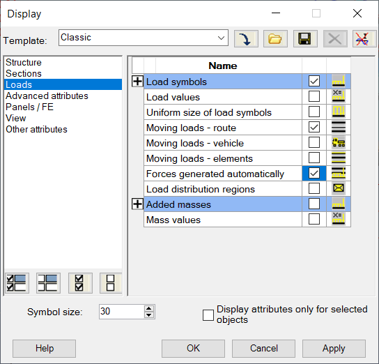
You can also visualize the pressure load distribution for finite elements (if not, the averaged method is used). Click View > Display and choose Loads on the left panel. Select Forces generated automatically in the display table.

If prompted, run a model generation in order to create the finite element mesh and apply the loads.