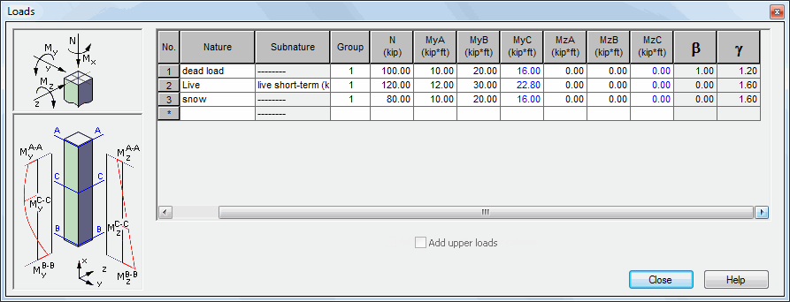
This option allows for column load definition. It is available from:
- the menu by selecting: RC element / Loads or
- the toolbar by selecting the Load Definition icon
 .
.
Once the option is selected, the dialog shown below will appear on the screen (the dialog below is for the ACI 318 code) .

In RC modules, you can work with loads in two ways:
- You can import a model to an RC module. In the Loads dialog, the load table fills out automatically with data imported from the model. You cannot edit the data then.
- You can define a model in the RC module and specify your data in the load table.
Column loads can be defined in the above dialog box. Depending on the calculation options selected, the user may define either only the compression force (the case of the column axial compression) or the compression force, moments (the case of the column compression and bending) and shear forces (the case with shear considered). It is also possible to automatically add upper loads. If the option Add loads from the upper column is selected (√ appears on the screen) loads from the upper column are added to the loads of the current column. Added loads are saved in the first rows of the column load worksheet and cannot be edited. When the option is deselected, upper column loads are skipped during column design process.
Column loads must be defined in order to activate the calculation options for a column. To run column calculations, each of the defined cases must have at least one non-zero component (N force or one of the moments); additionally - one of the load cases should contain a non-zero load force.
Changing loads erases recent calculation results and closes any previously open viewers which contained the results.
The N column displays longitudinal forces. After importing a model to the RC module, the N column displays the greater of the values of longitudinal forces from both column nodes.
The significant step while defining loads is to correctly define moments in a column. Fields in the load table for each of directions work in the following way:
- definition of values of moments at column ends; moments acting on the upper and lower end of the column are denoted by the symbols MA and MB; after entering a value in the upper and lower part of the column, the program calculates automatically the moment in the central part of the column, which is indicated by the symbol MC (a value of the moment is calculated according to the guidelines of a given code); a value of the MC moment is displayed in blue color

- a value of the moment in the central part of the column may be typed in by the user independently or the moment value calculated automatically by the program.
The exception includes a situation when for any of the load cases the MC moment is entered manually by the user. Then, the MC moment for a given combination is a sum of component MC moments of that combination.
Values of moments at the column ends and in the central part of the column are assigned to the column cross-sections (correspondingly to the upper, lower and central ones) which are designed separately for each combination. See also: RC column design procedure
If the Shear considered option (in the Calculation Options / Advanced dialog box) is active, then after entering a moment for the selected direction (e.g. Y), the program automatically calculates a shear force so that it corresponds to the linear distribution of the moment (for the MY moment it will be Fz). The Shear considered option is available only for several RC codes.
See also: