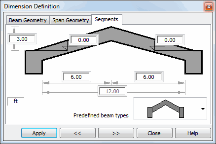
The dialog box shown below appears on the screen once the Segments tab is chosen in the Dimension Definition dialog box.

Options in the above dialog box are used to define selected shapes of a beam or to divide a beam into segments.
At the bottom of the dialog box there is a selection list including predefined beam types. After selecting a geometry model, selected dimensions can be edited in the fields provided in the schematic drawing of a beam; a number of dimensions depends on a selected beam type.
Note should be taken that while editing the length of one of segments of a span that consists of several segments, the total length of the span does not change (it corresponds to the value defined on the Span Geometry tab).
One of predefined beam types provided on the drop-down list is a table; selection of this type allows editing the segment dimensions in the form of a table. After choosing the table symbol in the dialog box there appears a table whose successive rows correspond to segments into which the beam span has been divided. The table fields enable modifying positions of the segment ends (X coordinate, Z coordinate). Edit operations for segments are available in the context menu (after pressing the right mouse button): Insert segment and Delete segment.
See also: