Clicking Advanced options in the Meshing options dialog lets you select new planar or volumetric FE mesh parameters.
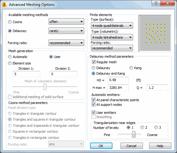
From the Allowable Meshing Methods field, you can select one of the following mesh generation methods:
You can also select the degree of method implementation for each type of mesh generation: never, rarely, or often. You can define the Forcing ratio. For example, if you select the Coons' method, define the implementation degree as often, and the forcing ratio as forced, the mesh generation algorithm forces the mesh to be created in the selected region according to Coons' method.
Also, you can define the Forcing ratio of the selected planar or volumetric FE type. For example, if you select 3-node triangles and Any as the forcing ratio, the mesh generation algorithm uses any type of planar or volumetric FEs when generating the mesh. You can also select the Triangle-into-quadrilateral conversion coefficient, which lets you define the parameter that is used when converting triangular elements into quadrilateral ones. In this field, you define a weight parameter using values from the range [-1, +1]. If you use +1 as a coefficient, rectangles are created from triangles in all possible places within the indicated area. This, however, can generate rectangles with incorrect shapes resulting in the ill-conditioning of a set of equations. If you use -1 as the coefficient, only those triangular elements that form a rectangle are changed. This coefficient is used when consolidating a mesh of finite elements. It is the same coefficient that you define in the Mesh consolidation dialog.
You can select either Automatic or User-defined for generating in the Mesh Generation field.
You can define two parameters: Division1 and Division2 for the Coons' method.
A division parameter for Coons' method, which defines the number of elements created on the second contour edge (between the second and the third contour vertexes). The edge of the contour is automatically divided so that the division corresponds to the first edge contour.
If you select Element size, you can define a dimension for an element in the finite element mesh to be obtained after the mesh is generated. For example, if the element dimension is 20 inches:
- Planar finite element (quadrilateral) mesh, generates a mesh of elements similar to a square, whose side is 20 inches
- Planar finite element (triangle) mesh, generates a mesh of elements similar to an equilateral triangle, whose side length is 20 inches
- Volumetric finite element mesh, generates a mesh of elements similar to a cube, whose side is 20 inches
Using the slider, you can select the type of volumetric finite element mesh to generate: from a coarse mesh to a fine mesh. If you select Additional meshing of solid surface when generating a mesh of volumetric finite elements, a mesh on a solid surface (contour) is also generated. Note when using this option, volumetric element mesh is finer.
You can select one of the following contour division types in the Coons Method Parameters field:
- Triangles in triangular contour
- Triangles and rectangles in triangular contour
- Triangles and trapezoids in triangular contour
- Squares in rectangular contour
- Triangles in rectangular contour.
You can also select the forcing ratio of the selected contour type for Coons' method.
You can select one of the following methods of mesh generation in the Delaunay's Method Parameters field:
- Delaunay's method only - Generates the mesh using only Delaunay's method.
- Kang's method - Generates the FE mesh only in the contour near the emitters, according to the accepted parameters of Kang's method (H0, Hmax, and Q).
- Delaunay's and Kang's method - Generates the mesh near the emitters according to Kang's method and outside of these contours according to Delaunay's method.
Emitters are special nodes defined at structure points that require more precise calculations, that is, a more refined finite element mesh. You can define the following emitters:
- At characteristic points of panels such as, panel corners and opening corners
- At nodes where supports are defined
- User-defined using the Emitters dialog.
The Kang parameters to increase the density of a finite element mesh include:
- H0 : The length of the first wave. It is used by default and in user-defined emitters.
- Kang's parameters (Hmax, Q)
- Hmax - The length of the penultimate wave before completing the process of increasing the size of mesh elements.
- Q - The relationship of the next wave length (Hn+1) to the previous wave length (Hn).
For example, if you specify the following parameters: H0=1.0, Q = 1.2, Hmax = 2.0, then waves of the following lengths are created: 1.0, 1.2, 1.44, 1.73, 2.07, 2.5.
See also:
Examples of creating finite element meshes (plates and shells)