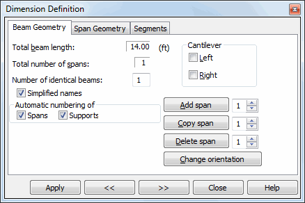
For RC beams, once this tab is selected in the Dimension Definition dialog box, the dialog box shown below will be displayed on the screen.
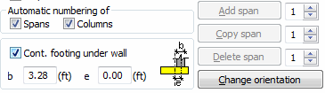
In the continuous footing module, the dialog box for definition of geometry differs in options available in the lower part of the dialog box.
The dialog boxes presented above are used to specify the name of a beam/continuous footing/deep beam and general information about geometry of the whole beam/continuous footing/deep beam concerning the: Total Beam/Continuous Footing Length and Total Span Number can be given.
It is also possible to add Left and Right cantilevers to the beam/continuous footing.
The following buttons are also to be found in the dialog box: Add Span, Copy Span and Delete Span..
In the lower part of the dialog box is the Change orientation button; pressing this button changes the direction of an RC beam (the beam beginning is now its end, while the end is its beginning).
In the lower part of the dialog box there are selection fields that allow switching on automatic numbering of supports and spans. If these options are switched on, then the program will automatically assign names to successive defined spans and supports; if the options are not switched on, then it is possible to assign user's own names to spans/supports on the Span geometry tab.
The Cont. footing under wall option available in the dialog box for continuous footings enable the user to define dimensions of a wall resting on a continuous footing. If a wall is defined on the entire length of the continuous footing, it is not necessary to check the condition for the bending capacity of the continuous footing.