Lets you import AutoCAD Civil 3D data into Civil View.
This panel reads an intermediate file format VSP3D (*.vsp3d). Civil View is capable of incorporating updates to VSP3D files into a visualization when a design change occurs in Civil 3D. See Civil View Object Updating for further details.
Generating VSP3D Files in AutoCAD Civil 3D
In order to generate VSP3D files from AutoCAD Civil 3D, you must have installed the Autodesk Civil View Exporter for AutoCAD Civil 3D.
Support for Civil 3D Object Types
Civil View currently supports the following AutoCAD Civil 3D object types:
- Surfaces
- Site/grading featurelines
- Corridor Featurelines (identified and split by corridor region)
- Corridor Baselines (alignment and profile)
- Corridor Surfaces (identified and split by corridor region)
- Corridor offset assembly featurelines
- Corridor offset assembly surfaces
- Point groups (supports point groups containing 1,000 points or less)
- Pipe Networks (excludes support for arched and custom pipes, and spherical structures)
- Alignments/Profiles (includes support only for layout profiles: that is, finished ground or design profiles)
Interface
- Open
- Click to open a file dialog and browse to the VSP3D file you want to use.
Important Notes
- Where multiple featurelines exist with the same name within a single corridor region or site, they will be combined into a single shape object containing multiple splines.
- All unnamed featurelines within a single site will be combined into a single shape object containing multiple splines.
- Import only objects that are likely to form part of the visualization. Importing objects that you do not need for visualization purposes will slow the performance of 3ds Max. You can always import additional objects at a later stage.
- Point groups containing up to 1,000 points are supported in Civil View. Point groups containing more than 1,000 points are listed in the Import Panel but are not available for selection and import.
- For pipe networks, arched and custom pipes are not supported and are therefore ignored.
- For pipe networks, spherical structures are not supported and are therefore ignored.
- Related layout profiles (sometimes known as design or finished ground profiles) are automatically associated with imported alignments. Civil View does not support surface profiles (sometimes known as existing ground profiles) or superimposed profiles.
[selection options]
This group of controls provides filtering options to help you select portions of one or more models.
- [string type drop-down list]
- Lets you choose either All Strings (the default), or one of the particular string types available in the active model.
-
 [check-mark button]
 - Click to select the strings that match your choice from the drop-down list.
-
 [X button]
 - Click to deselect the strings you have selected.
- [wildcard field]
- Lets you narrow the string selection by entering a wildcard expression. Default = * (select all).
You can also use the file contents list to select strings individually, or right-click the list to see a menu with additional selection options.
-
 [plus-sign button]
 - Click to select those strings that match the wildcard field.
-
 [minus-sign button]
 - Click to deselect those strings that match the wildcard field.
- [hierarchy view]
- Shows the full hierarchy of the Civil 3D data set. Click within this tree to select a parent object; for example, a specific corridor, corridor region, or site. The Civil 3D Import panel displays the children of that object in the list view to the right.
Right-click the hierarchy to open a menu that lets you select all objects that are children of the parent.
To see all objects in the list view, select the root node at the very top of the hierarchy.
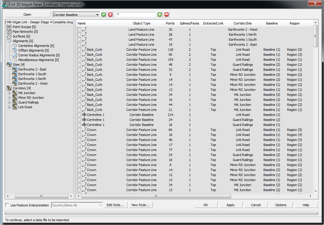
- [list view]
- Lists the objects are related to the parent object selected in the hierarchy.
Right-click the list view to open a menu with selection options such as matching name, object type, corridor, layer, or assembly.
This list includes the following columns of information:
- Name The name of the Civil 3D object.
- Object Type The type of the Civil 3D object; for example, surface, alignment, featureline, corridor surface, and so on.
- Points For shapes, the total number of points in the shape. For surfaces, the total number of vertices in the mesh.
- Splines/Faces For shapes, the total number of splines in the shape. For surfaces, the total number of faces (triangles) in the mesh.
-
Extracted Link The extracted link code that was specified during the export process from Civil 3D. Applies to corridor-related objects only.
The Civil View Exporter for Civil 3D allows the exported data from a corridor to be filtered by corridor link code. Usually you will use the link code "top" to ensure that only the top surface of a corridor is exported for visualization purposes.
- Corridor/Site The name of the parent or container to which the listed object is related. For corridor surfaces, alignments, and featurelines, the name of the corridor is listed. For site/grading feature lines, the name of the site is listed. Applies to corridor- and site-related objects only.
- Baseline The baseline to which the listed corridor object is related. Applies to corridor-related objects only.
- Region The region to which the listed corridor object is related. Applies to corridor-related objects only.
- Assembly The assembly that was applied to the region to which the listed corridor object is related. Applies to corridor-related objects only.
- Start Station The start station of the region or baseline to which the listed corridor object is related. Applies to corridor-related objects only.
- End Station The end station of the region or baseline to which the listed corridor object is related. Applies to corridor-related objects only.
- AutoCAD Layer The AutoCAD layer from which the listed object was extracted.
Some objects in the list might be appear grayed out. This can happen for one of a couple reasons:
- The object has already been imported into the current scene. Civil View automatically checks all object and model names against previously imported objects. If any identical object name or model name combination already exists in the current scene, the corresponding list item is disabled.
- The object type is not supported by Civil View.
[feature interpretation controls]
Use these controls to select a Feature Interpretation Style to apply to the imported strings.
Feature interpretation associates predefined Civil View object-creation styles with objects as they are imported. The range of style definition that can be referenced from a feature interpretation style include:
-
Swept Object Styles
-
Object Placement Styles
-
Road Marking Styles
-
Rail Object Styles
-
Building Object Styles
The application of feature interpretation removes much of the work associated with developing visualization models from civil-engineering design data. Guard rails, road markings, street furniture, railway tracks, and vehicles can all be placed in a scene completely automatically from a library of pre-defined styles.
If feature interpretation is not turned on, shape objects created from imported Civil 3D data are colored according to a color-matching table in the civilview.cfg file that ships with Civil View. This file can be customized, and is stored in the \plugcfg folder (there is a copy of this folder for each of the languages used by 3ds Max).
- Edit Style
- Click to open the Feature Interpretation Style Editor and load the selected predefined Feature Interpretation Style.
- New Style
- Click to open the Feature Interpretation Style Editor in order to start the creation of a new Feature Interpretation Style.
- Options
- Click to open the Import Options tab of the Civil View Preferences panel, where you can set a range of geometry import defaults, such as the mesh smoothing threshold angle.
Every Civil View object derived from Autodesk Civil 3D is assigned a primary default material channel that is assigned to any ungrouped or otherwise unidentified triangles. The default material channel for imported surfaces is also defined on the Civil View Preferences panel.