Displays information about imported surface objects, lets you update a surface, and "drape" a bitmap over a surface.
Data Source Tab
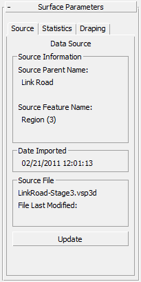
Displays information about the source of the imported surface.

Source Information group
If the Surface object was derived from imported triangulation (TIN) data, this group displays information relating to the imported surface.
- Source Parent Name
- Displays the originating model, site, corridor, or layer name. Typically this is the name of a 12D Model or MX model, a Civil 3D corridor or site, or an AutoCAD or MicroStation layer.
- Source Feature Name
- Displays the originating string or feature line label. Typically this is a 12D Model or MX string label, or a Civil 3D Feature Line label.
Date Imported group
Shows the date and time on which this object was created.
Source File group
- [source file name]
- Shows the name of the source file.
- File Last Modified
- Shows the date on which the source file was last updated.
If this date is later than the date on which the object was imported, the selected object might be out of synch with your current source design data.
This value is blank if the source file cannot be found.
- Update
- Updates the surface using the original source file. See Object Updating for further details.
Not available if the original source file is no longer found in the original path.
Tip: You can simultaneously update multiple objects using the Imported Object Manager.
Surface Statistics Tab
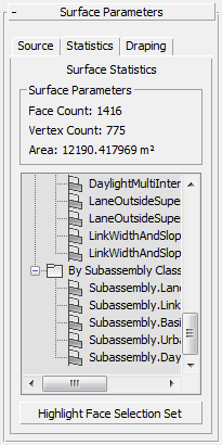
Displays a report on the attributes of the selected surface.

Surface Parameters group
Displays the following information:
- The number of faces (triangles) in the surface.
- The number of vertices in the surface.
- The total surface (slope) area of the surface.
- [detailed statistics list]
- Lists the surface's triangle/face selection sets. The primary selection set is a range of CivilViewSurfaces material channels used by the selected surface. This list provides an overview of the material types in use on the selected surface.
For imported AutoCAD Civil 3D Corridor Surfaces, a wide range of triangle/face selection sets is displayed, which relate directly back to the source corridor structure. This makes it possible to identify individual faces by originating link code, subassembly name and subassembly class.
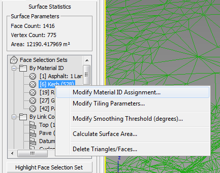
Right-click any displayed entry (see figure below) in order to:
- Change the material channel assignment for the selected triangles.
- Modify the material mapping parameters for the selected triangles.
- Remove the associated triangles from the selected surface.
- Calculate the surface area for an individual material type.

- Highlight Face Selection Set
- While on, faces in the current selection set are highlighted in 3ds Max viewports.
Bitmap Draping Tab
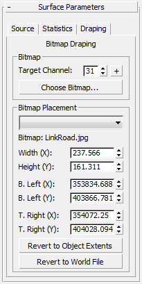
Provides a way to "drape" a bitmap over surface. Usually the surface represents the ground, and the bitmap is an aerial orthographic photograph.

Bitmap group
- Target Channel
-
In the CivilViewSurfaces material, channel 31 is reserved as the default channel for draped bitmaps. Therefore, controls on this rollout usually operate on faces or triangles using channel 31; however, you can drape bitmaps over faces using any material channel/ID.
- "+" button Click to add a new material channel to the CivilViewSurfaces material.
- Choose Bitmap
- Click to open a file dialog and choose a bitmap from any available directory on the current system.
Civil View supports georeferencing using the World File Format. If Civil View finds a World File whose file name matches the name of the bitmap you choose, the bitmap is draped over the surface using correct world coordinates. These coordinates appear in the Existing Placement Coord[inate]s group, although no manual editing should be required.
The World File must have the same root name as the bitmap file, and be saved in the same folder. Filename extensions for World Files depend on the bitmap format:
Image Type World Filename Extension *.TIF
*.TFW
*.GIF
*.GFW
*.TGA
*.TAW
*.CALS
*.CLW
*.PNG
*.PGW
*.BMP
*.BPW
*.JPG or *.JPEG
*.JGW
For further information on the World File format, visit http://en.wikipedia.org/wiki/World_file
Bitmap Placement group
- [material channel drop-down list]
- Lets you choose the material channel to use.
- Bitmap
- Displays the name of the bitmap.
- [coordinate and placement spinners]
- These interrelated spinner controls set the real-world position of the bitmap. You can position the bitmap by "bottom-left" and "top-right" coordinates. You can also position the bitmap by "bottom-left" coordinates in conjunction with Width and Length values. All six spinner values react to each other.
Notes:
- The default values for these coordinates are the extents of the surface.
- The bitmap is applied only to faces on the object that are assigned the chosen material channel. All other faces are unaffected.
- These controls take account of the current Civil View Global Shift Values as defined on the Scene Settings rollout. This means you need to specify true world coordinate values rather than local scene coordinates.
- When more than one set of draping coordinates is being used on the selected surface object, remember to use the drop-down list to select the correct material channel before making changes to the displayed draping coordinates.
- Revert to Object Extents
- Click to revert the to the default coordinates, which are based on the extents of the surface.
- Revert to World File
- Click to revert to the coordinates specified by the World File. If no World File is detected, Civil View uses the surface extents, instead.