Lets you place one or more objects along the path of a parent shape.
You can place objects in static positions, or animate them to move along the reference shape at a particular speed.
Object placement instructions that you specify in this panel can be saved to Object Placement Styles (OPS). This enables country-, organization-, or project-specific styles to be stored for later use.
You obtain object sources from Civil View object libraries in a series of Country, Project, and Private resource kits, which you can customize.
Interface
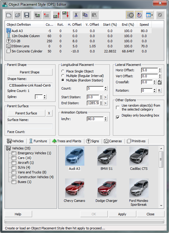
[OPS element list]

The OPS element list consists of a set of instructions to place a series of objects along the current reference shape. Each element in the list can either be an instruction to place a single object at a specific chainage, or a series of objects at regular or random chainage intervals.
For each element, you can specify Independent horizontal and vertical offsets from the reference spline, along with independent rotation and start/end chainages.
-
 Start New Style
 - Click to create a new Object Placement Style.
-
 Open Style
 - Click to open a previously created Object Placement Style.
-
 Save Style
 - Click to save the current Object Placement Style.
-
 Add new element
 - Click to add a new element to the current Object Placement Style.
-
 Delete selected element
 - Click to delete the selected element from the current Object Placement Style.
-
 Move selected element up
 - Click to move the selected element up by one position in the current Object Placement Style.
-
 Move selected element down
 - Click to move the selected element down by one position in the current Object Placement Style.
-
 Cut Element
 - Click to cut the selected element from the style, saving it to the Clipboard.
-
 Copy Element
 - Click to copy the selected element and save it to the Clipboard.
-
 Paste Element
 - Click to paste a cut or copied element.
You can paste a Cut element to a different location in the current style, and you can paste a Cut or Copied element to a different OPS.
-
 Wheel Rotation Status (Override)
 - Optionally, you can set the wheels of animated vehicles rotate appropriate to the speed of the vehicle at any given time.
Although this feature is controlled primarily from the Civil View Preferences panel, this override option lets you temporarily disable or enable it for the current Object Placement session. You might wish to disable wheel rotation to lessen the performance overhead when working with large numbers of animated vehicles. Depending on the location of cameras in your scene, it is possible that rotating wheels might not be visible from your chosen viewpoint in the scene.
Wheel rotation only works for vehicles in the Object Library that have been prepared to meet specific requirements. For more details, see Vehicle Library.
-
 Chainage Looping Status
 - The state of his button indicates whether the Civil View chainage looping feature is activated. Chainage looping causes animated vehicles to loop back to the beginning of the parent shape when reaching the end of a parent shape.
You can temporarily override the setting by changing the status of this button. The global setting for this feature is defined in the Civil View Preferences panel, and is on by default.
-
 Choose how to view Civil View Object Library content
 - Click to open a menu that lets you choose how to display content in the object list at the bottom of the dialog.
-
 Reset currently placed objects
 - Click to delete all objects placed in the scene from the current object placement session.
- [list of elements]
- Lists each element in the OPS, along with its style settings.
Parent Shape group
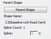
- Parent Shape
- Click to turn on, then click in a viewport to select a parent shape.
Until you select the parent shape, most of the controls on this panel have no effect.
The start and end stations of the shape you select are displayed in the Longitudinal Displacement group (see below), and are represented in the viewport by Dynamic Markers. All placed objects are generated at static or animated locations along the path of the parent shape.
- Shape Name
- Shows the name of the shape you chose.
- Spline Count
- Shows the number of splines in the parent shape.
- Spline
- For shapes that include multiple splines, lets you choose which spline to use for chainage placement.
You can change the Spline value. However, if you change the Spline value after a group of objects has already been placed, Civil View assumes that you wish to work on a new set of objects. The existing group of objects remains in the scene, aligned to the original spline.
You can use the Spline value to step through each spline in the parent shape, applying the current Object Placement Style to every spline.
Parent Surface group

- Parent Surface
- Click to turn on, then click in a viewport to select a parent shape.
Choosing a parent surface is optional. If you choose one, objects can align to the contours of the surface. The surface controls the Z-value of the object's XYZ position, so objects sit on the ground accurately. In addition, vehicles align to the slope of the surface so they tilt correctly to match varying carriageway crossfalls. (Objects that aren't vehicles always align vertically.)
Camera objects ignore the parent surface.
If you choose a parent surface, you should set the Vertical Offset (see below) to 0.0.
Choosing a parent surface for animated objects can slow performance.
- "X" button
- Click to remove the parent surface assignment.
- Surface Name
- Shows the name of the surface you chose.
- Face Count
- Shows the number of faces in the parent surface.
Longitudinal Placement group
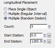
- Place Single Object (The default.) Places a single object at the Start Station location. Ignores the End Station value.
- Multiple (Regular Interval) Places multiple objects at a regular interval between the specified Start and End Stations. The Count value sets the spacing.
- Multiple (Random Chainage) Places multiple objects between the specified Start and End Stations with random spacing. The Count value sets the number of objects.
The actual position of the objects is assigned randomly every time you click Apply.
This option is useful for quickly placing vehicles.
- Count
- Sets either the spacing of objects when you choose Multiple (Regular Interval), or the number of objects when you choose Multiple (Random Station).
- Start Station / End Station
- Set the start and end station values along the length of the spline. Single-object placement uses the Start Station value only.
In viewports, the Start and End Station locations are indicated by Civil View Dynamic Markers. You can set the Start or End Station value by clicking the ">" button to the right of the spinner, then clicking a location in a viewport.
Tip: When you set the Start or End Station by clicking a viewport, the 3ds Max snap tools can be helpful.The Start and End Station values are completely independent between different OPS elements. For example, you can use this panel to place 20m double lamp columns over the first 80 percent of the spline, and then place 12m single columns over the remaining length.
Animation Options group

- km/hr
-
Sets a velocity for the object.
If this value is equal to 0.0, no animation keys are created and the object is motionless. The position of the object can be subsequently controlled by using the Position Controller rollout.
If you enter another value, Civil View creates animation keys so the object travels along the parent spline. Typically you use this to animate vehicles and drive-through cameras moving along a highway or railway.
- A positive value moves the object moving along the parent spline at a constant speed in a forward direction.
- A negative value moves the object along the parent spline at a constant speed in the opposite direction.
If you use a negative value, set Rotation to 180 degrees so the vehicle doesn't travel backwards.
If the current animation length in the scene is not sufficient for the object to travel the specified distance at the specified speed, Civil View can adjust the scene animation length. It asks whether you want to do so. If you leave the animation length unchanged, the end point of the moving object is adjusted to suit the amount of available time.
Tip: To vary the speed of an object after placement in the scene from this panel, see Position Controller.You can also use Track View to edit the default animation keys; for example, to animate lateral changes in position on the road or changes in vehicle speed.
Lateral Placement group

- Horiz[ontal] Offset / Vert[ical] Offset / Crossfall
- Set the position of the object relative to the reference spline.
The values of these controls are dynamically linked so that changing one value affects another. This lets you choose, for example, whether to specify vertical offset by Offset or Crossfall while being able to see both values. If you know the required crossfall, set that value first, then change the Horizontal Offset to watch the Vertical Offset value update accordingly.
If a parent surface is active, the Vertical Offset is relative to the surface at the object's current location. Otherwise, it is relative to the parent shape level at its insertion point. If you use surface tracking, leave Vertical Offset set to 0.0.
-
 [lock crossfall] Locks the Crossfall (% slope) value, so that changing the Horizontal Offset causes the Vertical Offset to change based on the specified slope. If Crossfall is unlocked, changing the Horizontal Offset causes the Vertical Offset to stay static, but the Crossfall value changes. Default=unlocked.
 The Vertical Offset value must be nonzero for the Crossfall lock to have an effect.
-
- Rotation
- Rotates the object in local space, relative to the parent spline insertion point.
-
"R" button When on, uses a random rotation value.
Random rotation is useful for placing trees.
-
"R" button When on, uses a random rotation value.
Other Options group

- Use random object(s) from the selected category?
- Object categories are divided into sub-groups that can also be selected for placement. When on, selects the parent group instead of the individual object definition. Objects within the group are then selected randomly for placement in the scene.
This option is useful for populating a highway with randomly selected vehicles.
- Display object bounding box only?
- When on, represents the object in all viewports by displaying only its bounding box, rather than complete geometry.
Turning on this option can improve viewport performance. This setting has no effect on the final rendered output of the scene.
This feature is particularly useful when you place vehicle objects in the scene, as these tend to have complex geometry.
[OPS element editor]
The lower portion of the OPS Editor lets you view and manage individual elements.
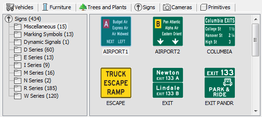
- [type tabs]
- Select the type of object you wish to place: Vehicles, Street Furniture, Trees And Plants, Signs, Cameras, or Primitives.
- [library list]
- Lists object categories of the active type in the current object library. Object libraries are provided by the current resource kit (which you open using the OPS element list controls at the top of the dialog).
- [object list]
-
Lists individual objects in the current category.
Right-click an object definition to open the Resource Kit Manager. The Resource Kit Manager lets you edit the object parameters.