Provides control over the static and animated position of an object, relative to the geometry of the object's parent shape or surface.
Tracking Tab
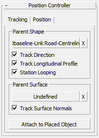
Parent Shape group
- [parent shape button]
- The position of the object is defined by the path of its parent shape. Click this button to choose an alternative parent shape. The object moves to a new position defined by the path of the new parent shape.
Changing the parent shape does not remove the object's link to its peers from the same instanced object set (see below for details).
- "X" button
- Click to make the object independent. It is no longer a child of the parent shape, and now its position is controlled by a standard XYZ Position controller.
- Track Direction
- When on, the rotation of the object follows the tangent of the reference shape at the object's insertion point. Normally you will turn on this option for objects like lamp columns and vehicles, which need to always follow the direction of their parent shape. Turn it off for objects like trees, which can have randomly applied rotation.
- Track Longitudinal Profile
- When on, the object tilts to take account of the vertical slope of the parent shape at the object's insertion point. When off, the object always remains truly horizontal. Normally you will turn this on for vehicles, which always need to take account of the longfall (slope) of their parent shape. Turn it off for objects like lamp columns and trees, which always remain upright.
Track Longitudinal Profile is ignored if Track Surface Normals is on (see below).
- Station Looping
- When on, animated objects return to the start of the parent shape when they reach the end of an animation sequence (assuming that sufficient frames are available for this to happen). Tip: The default station looping setting in Civil View is defined in the Civil View Preferences panel.
Parent Surface group
As well as following the path of a shape, objects can also track surface terrain. This effectively overrides the Z value (or object height) derived from the parent shape. This feature ensures that objects always sit perfectly on a ground surface, but you should use it sparingly. It can have a severe effect on the performance of 3ds Max, particularly with animated objects.
This group of controls is available to all objects except camera objects. Camera positions can be controlled by parent shapes only.
- [parent surface button]
-
Click this button to select a parent surface, or to change the current surface assignment.
- "X" button
- Click to make the object no longer a child of the surface.
- Track Surface Normals
-
When on, the object tilts to match the slope of the underlying surface. This is particularly useful for ensuring that vehicles on a road surface always automatically "ride" over varying crossfall without the need for specific animation instructions. In general, turn this option off for items of street furniture, which are almost always placed upright.
Position Tab
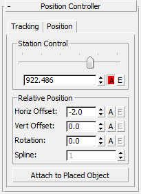
Station Control group
- [slider and spinner]
- Control the longitudinal position of the object along the parent shape. Use the slider control for coarse changes to position, and the spinner to make finer adjustments.
The station is measured from the start of the currently selected spline in the current shape object.
Relative Position group
- Horiz[ontal] Offset
- Sets the horizontal offset from the parent shape. This value is expressed in world units.
- Vert[ical] Offset
- The effect of this spinner depends on whether a parent surface is active:
-
If you haven't specified a parent surface, the vertical offset is relative to the Z value of the current position on the parent shape.
-
If you have specified a parent surface, and a portion of that surface is found under the current position of the object, then the vertical offset is relative to that surface. If you have specified a parent surface but Civil View cannot detect the surface under the current object position, the vertical offset is derived solely from the parent shape.
-
- Rotation
- Sets object rotation at the object's current position. Rotation is expressed locally, which means that it is applied in addition to any rotational value derived from parent shapes and surfaces. Therefore, a value of 45 degrees specified here will generally result in the object always being oriented at 45 degrees to the parent shape direction at the insert position. If the Path Rotation feature is not active, rotation is applied from the direction of north.
- Spline
- A single parent shape can contain several splines (this is similar to the use of discontinuities in MX). This spinner controls which spline within the parent shape the object should be assigned to. Chainage values used relate to the distance from the start of the currently selected spline, not from the start point of the entire shape object.
This spinner is available only when the parent shape contains more than one spline.
- Attach to Placed Object
- As well as being controlled by the path of a parent shape, objects can also be attached to other objects which in turn are controlled by parent shapes of their own. This means that a single object could control the position of a series of child objects. For example, this feature can be used to attach a series of signs to a gantry object, so that if the position of the gantry is ever changed, the signs are always relocated accordingly.
To use this option, click this button and pick a new parent object that you would like the current object to be attached to. The Position Controller rollout in the Civil View Explorer panel will then be replaced by the Attachment Controller rollout, which offers the ability to locally offset the newly attached object from its new parent object.
Animation Controls
You can animate the chainage, offset, and rotation settings. To do so, use the "A" and "E" buttons adjacent to these parameters.
- "A" button: Animation Mode
- If you have animated the parameter, this button is on.
If the object is not currently animated, click this button to add a constant animated value to the parameter. The animation can then be edited in more detail using the "E" (Edit Animation) button.
To remove animation from this parameter, click the button to turn it off.
- "E" button: Edit Animation
- If you have animated the parameter, this button is enabled. The default, constant animation creates two keys.
Click this button to open the Civil View Animation Editor. In this dialog, you can edit the keys. The possibilities include:
- Varying the speed of the object.
- Varying horizontal offsets so vehicles change lanes on a dual carriageway.
- Varying vertical offset and rotation for drive-through and fly-through cameras.