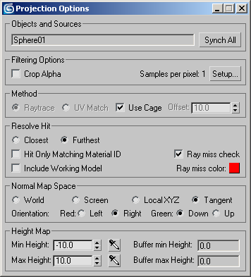
This dialog displays options for normal bump projection.
Objects and Sources group
The text field displays the name of the projection's source object. If more than one object is selected, it displays the source option chosen in the Render To Texture dialog: a single object name for Individual, or “All Selected” (the default), or “All Prepared.”
- Synch All
- Click to set all Render-To-Texture sources to use the active source object and the other current Projection Options settings. This button is available only when there is an individual source object.
Filtering Options group
- Crop Alpha
- Removes antialiasing from the alpha channel.
- Global Supersampler
- When the default scanline renderer is active, the text field shows the type of global supersampling that is currently in use. Default=None.
- Setup Click to set up global sampling. When the default scanline renderer is active, clicking Setup displays the Render dialog's Default Scanline Renderer rollout, whose Global Supersampling group lets you globally enable supersampling, and choose the supersampling method.
Method group
These controls let you choose how to use normals from the source object.
- Raytrace (The default.) When chosen, normals are ray-traced between the source and target objects. The objects need to be perfectly aligned in world space. When you view both high-res and low-res objects in viewports, they must line up with each other exactly. There are no special requirements for the mapping coordinates of the high-res objects.
-
UV Match When chosen, normals are obtained by matching the target object's local UV coordinates to those of the source. The objects' UV coordinates need to be perfectly aligned. If you look at the objects using the Unwrap UVW modifier's Edit UVWs dialog, the low-res and high-res objects must be lined up with each other exactly. The high-res object needs to have mapping coordinates on the same map channel you are using for the low-res object.
Typically, the high-res object will have an Unwrap UVW modifier assigned to it, but this is not required.
With this option, the high-res object does not need to be in the same physical location as the low-res object.
Tip: You can reset the cage (on the Cage rollout), because UV Match does not use it.
- Use Cage
- When on, bases projection on the Projection modifier's cage sub-object. When off, uses an offset instead. Default=on.
- Offset
- Enabled only when Use Cage is turned off. Offset is the distance above the surface of the source object from which normals are projected. Default=10.0 units.
Resolve Hit group
The two radio buttons are for scenes that have semitransparent objects, in which case more than one hit can be found for each ray. The remaining controls in this group are additional projection controls.
- Closest If there are multiple hits, use the closest object.
- Furthest (The default.) If there are multiple hits, use the farthest object.
- Hit Only Matching Material ID
- When on, projection is only between material IDs that match. Turning this option on enables a single map to contain normal bump projections from different high-res source geometry. Default=off.
- Include Working Model
- When on, bakes from the source object if no target object can be found. Default=off.
Turning on Include Working Model can be a quick fix when a lot of the projected rays miss the target object (the Ray Miss Color will be apparent in the rendered normals map). However, if the low-res object occludes the high-res object, then Include Working Model will not have the desired effect, and the normal map will not show high-res details that you want it to. In this case, adjust the Projection modifier's cage.
This toggle is also useful when the high-res geometry is discontinuous (for example, a lattice or an array of cylinders).
- Ray miss check
- When on, bakes missed rays as well as rays that hit into the rendered texture, using the Ray Miss Color. Default=on
- Ray miss color This color is baked into the texture when projection fails to hit the target geometry. Click the color swatch to display a Color Selector and change the color used for missed rays. Default=red.
Normal Map Space group

There are four methods for projecting the normals:
- World Project using world coordinates. This is useful mainly for objects that don't move or deform; otherwise, a moving object with world-projected normals will appear to “swim” through the texture.
- Screen Project using screen coordinates; that is, flat projection in the Z axis. This method is useful mainly for stationary objects seen from a single angle only; for example, a statue seen through a window.
- Local XYZ Project using the object's local coordinates. This method can be used for stationary or moving objects, but not for objects that deform: if the object deforms, the projection will appear incorrect at some frames.
- Tangent (The default.) Project at a tangent to the target object's surface. This is the method to use for objects that both move and deform, such as animated characters.
- Orientation
- The orientation settings determines what the red and green colors will indicate in your normal map. The orientation settings are different for the Tangent method than for the other methods.
The correct setting for red and green depend on what kind of hardware shader or texture will be used to view the map. Different shaders have different requirements. The Normal Bump map has controls to flip the red and green; the Normal Bump texture should work correctly if the map was created with the default X and Y or Left and Right settings, but if the map was created with different settings, change the Normal Bump settings to make the map render correctly, instead of rendering a whole new map.
Projection method = Tangent

For the Tangent method, red indicates normals that are pointed either left or right and green indicates normals that are pointed up or down.
As an example, if you use Tangent mode with Red set to right and Green set to down, areas that are red in your normal map would indicate that the normals were facing towards the right and areas that were green would indicate that your normals were facing downwards.
The following are the possible values for the Tangent method:
- Red Can be Left or Right. Default=Right.
- Green Can be Up or Down. Default=Down.
Projection method = World, Screen, or LocalXYZ

For World, Screen, and LocalXYZ, red indicates that the normals are pointed toward either a positive or negative X value, while green indicates that the normals are pointed toward either a positive or negative Y value.
For example, if you use World mode with Red set to –X and Green set to –Y, areas that are red in your normal map indicate that the normals face toward –X, and green areas indicate that the normals face toward –Y.
The following are the possible values for World, Screen, and Local XYZ methods:
- Red Can be –X or +X. Default=+X.
- Green Can be –Y or +Y. Default=+Y.
Height Map group
- Min Height
- Sets a minimum height for displaced normals. Default=0.0 units.
- Max Height
- Sets a maximum height for displaced normals. Default=10.0 units.
-
 Min and Max Height eyedropper
- Enable the eyedropper to pick the minimum or maximum height for the displaced normals by picking or dragging in a viewport. With the button enabled, click at the desired height. You can also drag this value until the desired result is achieved. The minimum or maximum height value is updated based on your selection.
- Buffer min Height
- After you render a normal bump projection, this value is set to the minimum distance that a projection ray travelled. Default=0.0.
- Buffer max Height
- After you render a normal bump projection, this value is set to the maximum distance that a projection ray travelled. Default=0.0.
If you want to use the Height Map texture element, you can render a normal bump map to obtain the Buffer values, and then set Min Height and Max Height accordingly, in order to get the best-looking possible Height Map.