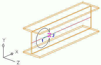
A circular contour is cut from the beam. It can be an outer or inner contour. The circular contour is defined by entering a center point and a second point defining the circle's radius.

Note: The circular contour depends on the position of the coordinate system. The contour is created parallel to the UCS. To cut a circular contour from a curved beam it is recommended to insert a coordinate system at a point of the object. When the beam is manipulated (e.g. using the grips), the contour is still assigned to the selected beam end and it maintains its distance to the end.
Access the command
Features tool palette:
 (Circular contour, 2 points, UCS).
Command line: _AstM4BeamContourNotchCircle2Dig
Create a circular contour using two points
- Select a suitable UCS.
- From the Features tool palette, select
 (Circular contour, 2 points, UCS).
- Select a beam at a reference end.
- Define the contour center point.
- Identify a point to define the circle radius.
- The circular contour is created with a default radius. The properties dialog box appears. You can modify the radius, gap, width and grid values.