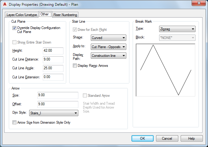
Use this procedure to specify other display properties for an individual stair, such as how to display the arrow in the path, which Display Path to show, and what type of break mark to use in the stair display. These display properties apply only to display representations, such as Plan, that are used in the Top view (plan view) of a drawing.
- Double-click the stair you want to change.
- On the Properties palette, click the Display tab.
- Under the General category, for Display component, verify that *NONE* is selected.
- For Display controlled by, select This object. Note: To apply your changes to all stairs in the drawing, select Drawing default setting. To apply changes to all stairs of this style, select Stair Style:<style name>.
- If necessary, expand Object Display Properties
 Advanced, and click
  next to Additional properties.
 - Specify the additional display properties for the stair:
If you want to… Then… change the display size of the arrow and break mark enter a value for Size. change the offset location of the arrow display enter a value for Offset. change the dimension style used for the arrow display select a style for Dim Style. Note: If a dimension style other than Standard is used for the arrow, and you want the arrow size to be controlled by the dimension style, select Arrow Size from Dimension Style Only. This is the default for all previous version drawings. If you do not select this option, the size of the arrow is multiplied by the arrow size setting.change the shape of the stair line select a shape for Shape. Curved adds an arc when the stair line changes. Straight displays an angle when the stair line changes. display the arrow at the end of each cut plane pointing in the same direction throughout the length of the stair select Cut Plane - Parallel for Apply to and make sure that Draw for Each Flight is not selected. display the arrow at the end of each cut plane and at the end of each flight pointing in the same direction select Cut Plane - Parallel for Apply to and make sure that Draw for Each Flight is selected. display the arrow at the end of the entire stair select Entire Stair for Apply to and make sure that Draw for Each Flight is not selected. display the arrow on each side of the cut plane select Cut Plane - Opposite for Apply to. change which stair line is displayed select Graphics path or Construction line for Display Path. change the type of break mark that is displayed at the cut plane under Break Mark, select a mark for Type. specify a custom break mark to display at the cut plane select Custom Shape for Type, and then select a block for Block. - Click OK.
You can also access and modify these same settings through the stair’s context menu, as follows:
- Select the stair you want to change, right-click, and click Edit Object Display.
- Click the Display Properties tab.
- Select the display representation where you want the changes to appear, and select Object Override.
The display representation in bold is the current display representation.
- If necessary, click
 .
. - Click the Other tab.

- Specify the additional display properties as needed.
- Click OK twice.