Use this procedure to add rectangular layout grids.
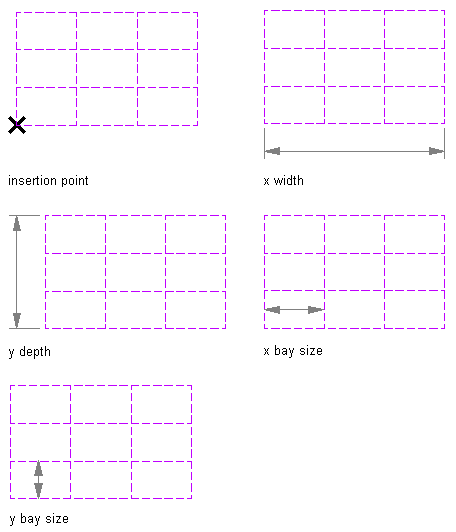
Rectangular layout grid parameters
- Open the tool palette that contains the layout grid 2D tool you want to use, and select the tool. Tip: You may have to scroll to display the desired tool. After selecting it, you can move or hide the Properties palette to expose more of the drawing area.
If there are no layout grid 2D tools available on tool palettes in the workspace, you can use the Content Browser to access the Stock Tool catalog, which contains a layout grid 2D tool under Parametric Layout and Anchoring Tools. You can add this tool to any tool palette.
- On the Properties palette, expand Basic, and expand General.
- For Shape, select Rectangular.
- Specify the boundary object attached to the grid, if necessary.
- Expand Dimensions, and select Yes to specify dimensions on the drawing screen or No to specify dimensions on the Properties palette.
- Enter values for the X-Width and Y-Depth properties.
- Expand X Axis.
- For Layout type, select Space evenly, and enter values for Number of bays and Start and End offset, or select Repeat, and enter values for Bay size and Start and End offset.
- Expand Y Axis.
- For Layout type, select Space evenly, and enter values for Number of bays and Start and End offset, or select Repeat, and enter values for Bay size and Start and End offset.
- Specify an insertion point in the drawing for the lower-left corner of the rectangular layout grid.
- Specify the rotation of the rectangular grid about the insertion point.