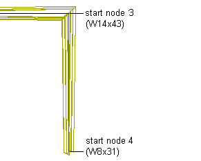
Use this procedure to create the second leg of the rigid frame by assigning a different start and end shape to the final segment of the rigid frame member.

Creating the second leg of the rigid frame
- Click Add to add a fourth component to the structural member.
- Select Unnamed under Component, and enter Leg 2.
- Under Start Shape, in the Name list, select W14X43.
- Select Start for Relative to.
- Enter 3 for Node.
- Scroll to the end of the Design Rules dialog box to display the End Shape parameters for Leg 2.
- Under End Shape, in the Name list, select W8X31.
- Select Start for Relative to.
- Enter 4 for Node.
- Click OK.
The complete rigid frame displays in your drawing.