Use this procedure to create a rigid frame, a multi-segmented structural member created from multiple shapes that transform at each vertex of the structural member path.
To create the rigid frame, you convert a multi-segmented polyline to a structural member and assign different start and end shapes to each segment of the member as components in the design rules of the rigid frame style. A series of nodes correspond to the start point, vertices, and the endpoint of the member path. By assigning different shapes to segments between nodes on the member path, the rigid frame transforms from one shape to several shapes along its path.
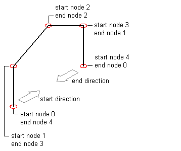
Assign shapes to the rigid frame member relative to the start of the member. The start point is defined as Node 0. The first vertex of the member is defined as Node 1, the next vertex is Node 2, and so on until the endpoint of the member, which is defined as the end node.

Identifying nodes on the member path
- Create two styles in the Structural Member Catalog that contain the shapes that transform over the path of the rigid frame.
- Create a rigid frame style and tool.
- Draw a multi-segmented polyline path for the rigid frame and use the rigid frame tool to convert the path to a structural member.
- Create the first leg of the rigid frame by assigning start and end shapes to the first segment of the frame.
- Create the first rafter of the rigid frame by assigning start and end shapes to the second segment of the frame.
- Create the second rafter of the rigid frame by assigning start and end shapes to the third segment of the frame.
- Create the second leg of the rigid frame by assigning start and end shapes to the fourth segment of the frame.