Use this procedure to create the first leg of the rigid frame by assigning a different start and end shape to the first segment of the rigid frame member.
Creating the first leg of the rigid frame
- Select the rigid frame.
- Select the column, and click
 .
. 
- Click Design Rules.
- Click Show Details.
- Select Unnamed under Component, and enter Leg 1.
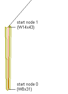
- Under Start Shape, in the Name list, select W8X31.
- Select Start for Relative to.
- Enter 0 for Node.
Node0 is relative to the start point of the member path.
- Enter 90 for Rotation.
- Scroll to the end of the Design Rules dialog box to display the End Shape parameters for Leg 1.
- Under End Shape, in the Name list, select W14X43.
- Select Start for Relative to.
- Enter 1 for Node.
Node 1 corresponds to the vertex formed by the endpoint of the first segment of the member path and the start point of the second segment of the member path.