Use this procedure to create AutoCAD blocks to represent each view of the multi-view block definition in display representations.
- Draw the views you need for a specific display representation:
If you want to… Then… create views for the front and back directions draw them on the XZ plane. create views for the left and right directions draw them on the YZ plane. create views for the top and bottom directions draw them on the XY plane. create a block for an interference condition create a block containing objects, such as mass elements, to be used as the subtractive body. - Specify additional insertion points on the Defpoints layer through the AutoCAD point command, if necessary. Note: The points added to view blocks are cumulative. For example, if you add one point to a view block used for the top view and two points to the view block used for the model view, you have a total of four points to cycle through. The fourth point is the regular base point defined during the creation of the block.
- Select the World Coordinate System before making blocks from these individual views.
- Define each view as a block, and coordinate the location of the insertion base point as you define each block.
For example, if you specify the insertion base point of the model view block as the midpoint of the bottom edge on the back side, the front and back view blocks have an insertion base point at the midpoint of the bottom edge. Then, the left and right view blocks have an insertion base point at the bottom corner on the back side, with the insertion base point for the top and bottom view blocks at the midpoint of the back edge.
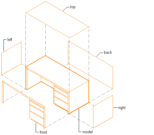
Creating individual blocks for multi-view block definition
Tip: It is helpful to have a naming convention for saving views as blocks. For example, name the plan view block desk-p, and name the right view block desk-r.