Slab and roof slab edge styles control the appearance of the edges of slab and roof slab objects. Using edge styles, you can specify dimensions, such as the overhang length, and the orientation and angle of the edges. You can also specify a fascia and soffit for the edge style.
Components of Slab/Roof Slab Edge Styles
The slab or roof slab edge style defines the appearance of slab or roof slab edges. Each style consists of two optional components: a fascia and a soffit.
A fascia is a shape applied to the outside face of a slab or roof slab edge. A soffit is a shape applied to the underside of an edge overhang.
You can create fascia and soffit components by defining profiles that provide the two-dimensional (2D) geometry of the component whose shape is then extruded along the slab or roof slab edge.
The fascia component follows the orientation of the slab edge (plumb or square cut). The soffit component, however, is always oriented to the horizontal. Either component can have a positive or negative angle, relative to its base orientation.
The +/- directions for edge component angles remain the same regardless of their orientation in the XY plane. They always follow the slab or roof slab slope, so that, for example, a +30° soffit and a +30° slab or roof slab would be parallel to each other. Similarly, a +10° (plumb cut) fascia and a -10° soffit would meet at a right angle. Mirroring a slab or roof slab maintains the same angle signs for all components.
Controlling the Placement of the Fascia and Soffit on Slab/Roof Slab Edges
The fascia profile is drawn at actual size, except when you select Auto-Adjust. If the slab or roof slab edge is sloped relative to the ground plane, then the length is measured parallel to that slope, and not plumb with the ground. When you select Auto-Adjust to Edge Height, the fascia profile is scaled about its insertion point so that its lowest Y axis point aligns with the bottom of the slab or roof slab edge.
The soffit profile is drawn at actual size, except when you select Auto-Adjust. The soffit angle is measured about its insertion point, using the local X axis of the profile.
When you select Auto-Adjust to Overhang Depth, the soffit profile is scaled about the insertion point, so that the furthest X axis point aligns with a plumb line from the slab or roof slab baseline or perimeter line. Auto-Adjust scaling is adjusted by the horizontal offset from the baseline dimension.
Display Properties of the Fascia and Soffit
In most cases, you want the appearance of fascias or soffits that use the same edge style to be consistent throughout a drawing. To achieve this, you specify the following display properties in each slab or roof slab edge style:
- The layer, color, and linetype of slab or roof slab edge components
- The hatching used for the surface of slab or roof slab edges in plan views
- The cut plane height
Slab edge components with display properties include dimensions for slab thickness, fascia and soffit, vertical and horizontal offsets, line work, cut planes, cut lines, 3D shading factors, baseline, slab, and pivot point. The display properties of the fascia and soffit are also controlled by slab or roof slab style, although the geometry of these components is controlled through slab or roof slab edge styles.
Materials in Slab/Roof Slab Edges
You can assign materials to a slab or roof slab edge. These materials are then displayed in wireframe or rendered views. Materials have specific settings for individual components of a slab or roof slab edge, such as the fascia and soffit.
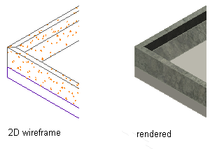
Viewing Slab Edge detail in 2D wireframe and rendered views
AutoCAD Architecture 2022 toolset provides predefined materials for common design purposes. These materials contain settings for slabs and slab edges that you can use “as is” or modify for special designs. You can also create materials from scratch.
Managing Slab/Roof Slab Edge Styles
To create, import, export, or edit styles, you use the Style Manager. The Style Manager provides a central location where you can work with styles from multiple drawings and templates.