Use this procedure to import LandXML data.
When you import a LandXML file, you can select different object types to import. Depending on the object type, you can define additional conversion parameters. For example, if you want to import LandXML parcels, you can choose to convert them to space objects or standard polylines.
Note: A LandXML file contains information about the drawing units in which it is measured. When you import a LandXML file into a drawing with different units, the LandXML data is converted to the units in the current DWG. When a LandXML file based on meter units is imported into a drawing based on millimeters, the resulting coordinates may exceed the range in which accurate calculations can be made.
- Click
 .
. 
- Select a LandXML file to import, and click Open. Note: If you have selected an invalid LandXML file, an XML file not based on the LandXML Schema, or an XML file based on a LandXML Schema version earlier than 1.1, you receive an error message and cannot import the file. Select another file that conforms to the LandXML 1.1 schema, or update the existing file accordingly.
- In the Import LandXML Data dialog box, select the import options.
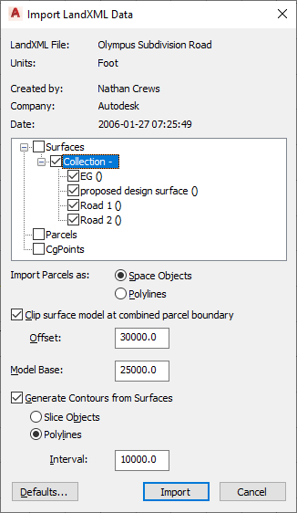
If you want to… Then… import surfaces from the LandXML file select Surfaces. This selects all surfaces from the imported file. To import only individual surfaces, expand Surfaces, expand Collection, and then select the surfaces you want to import. import parcels from the LandXML file select Parcels. This selects all parcels from the imported file. To import only individual parcels, expand Parcels, expand Collection, and then select the parcels you want to import. import COGO points from the LandXML file select CgPoints. This selects all COGO from the imported file. To import only individual points, expand CgPoints, expand Collection, and then select the points you want to import. - If you are importing parcels, indicate the form to which you want them converted by selecting either Space Objects or Polylines.
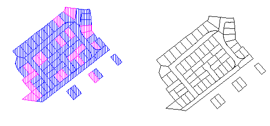
Parcels converted to spaces (left) and polylines (right)
- If you want to clip the surface model using the boolean union of all parcels as the model boundary, select Clip Surface Model at Combined Parcel Boundary.
If this check box is selected, you can also enter an offset from the boundary.
- Enter a value for Model Base.
This creates an extrusion of the surface outer boundary from the value you enter starting at the lowest surface point.
- If you want to generate contours from the surface data you are importing, select Generate Contours from Surfaces. Note: If you want to see the actual surfaces of the converted mass element, such as a TIN model, you can display the mass element without Gouraud shading.
- Indicate how you want the contours to be created by selecting either Polylines or Slice Objects.
- Enter an interval value for the vertical spacing of the contours. Note: Because slice objects shade their entire area, they can interfere with the appearance of the surface itself in shaded or hidden line views.
- Click Import.